Goodrive35 inverters Basic operation instruction
185
V /F curve
Linear V/F curve
Multi-dots V/F curve
Self-defined V/F curve
2.0th power of torque V/F curve
1.7th power pf torque V/F curve
1.3th power of torque V/F curve
PWM output
Frequency setting
Voltage setting
P04.29 voltage ACC time
P04.30 voltage DEC time
P04.31 output Max. voltage
P04.32 output Mini voltage
P00.11 ACC 1
P00.12 DEC 1
P00.04 upper limit of the running
frequency
P00.05 lower limit of the running
frequency
P04.00 motor 1V/F curve setting
0
1
2
3
4
5
6
7
8
9
10
Keypad
AI1
PROFIBUS
MODBUS
PID
Multi-stage speed
HDI
AI3
AI2
Erthernet
CAN
P04.27(voltage setting channel selection)
Keypad setting voltage
P04.28
0
1
2
3
4
5
6
7
8
9
10
11
Keypad
AI1
PROFIBUS
MODBUS
PID
Multi-stage speed
Simple PLC
HDI
AI3
AI2
Erthernet
CAN
P00.06
( A frequency command selection(
Keypad setting frequency
P00.10
0
1
2
3
4
5
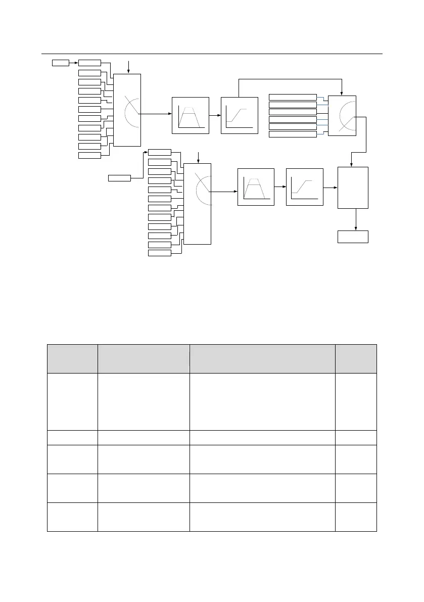
When the user selects the user-defined V/F curve function in Goodrive35 series inverters, they can
set the given channel of voltage and frequency and the corresponding ACC/DEC time, or the two
can combinate to form a real-time curve.
Note: the application of V/F curve separation can be used in many cases with various kinds of
power supply of the inverter. But the users should set and adjust the parameters with caution.
Incorrect parameters may cause damage to the inverter.
Detailed instruction of parameters
0: Sensorless vector control mode 1
1: Sensorless vector control mode 2
2:SVPWM control
3: Close loop vector control mode
Upper limit of the running
frequency
Lower limit of the running
frequency

 Loading...


