Goodrive35 inverters Basic operation instruction
193
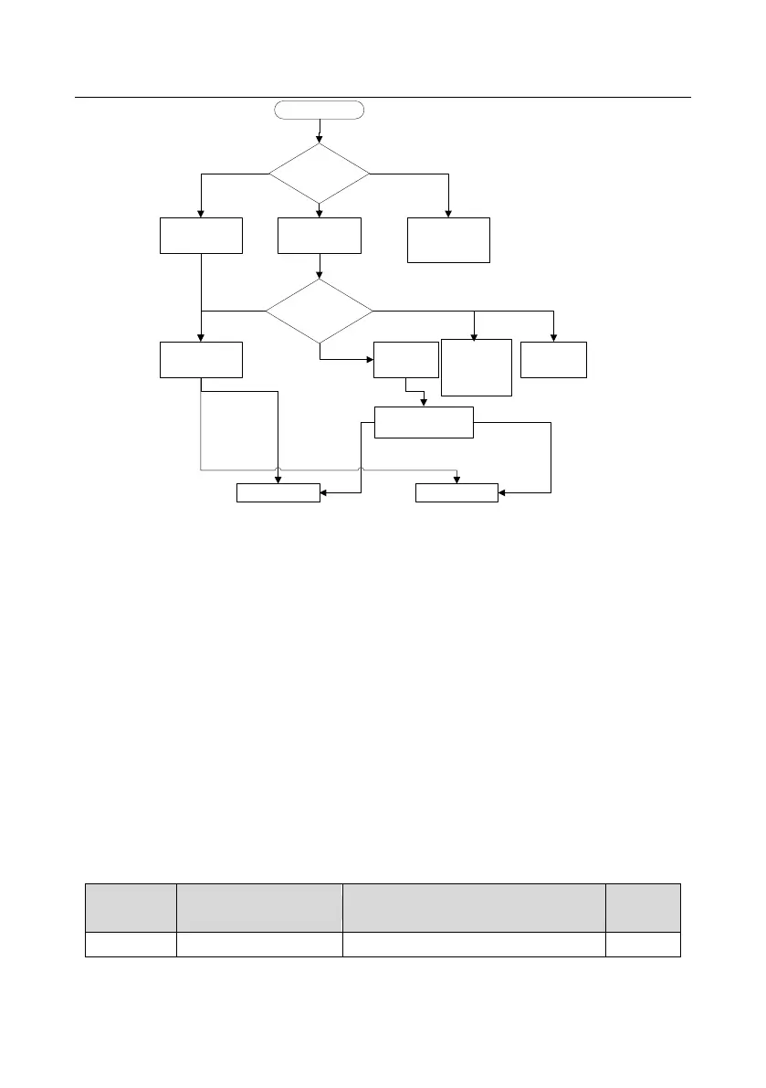
Keypad running
command
(P00.01=0)
Terminal running
command channel
(P00.01=1)
Communication
running command
channel
(P00.01=2)
MODBUS
communication
channel
PROFIBUS
CANopen
communication
channel
Start
Select Run
command channel
(P00.01)
Motor shifting
(P08.31)
Terminal 35
Motor 1 shift To
Motor 2
communication setting
2009H
Motor 1 Motor 2
Invalid
Valid
BIT0~1=00
BIT0~1=01
P08.31 LED
ones set 0
Ethernet
communication
channel
P08.31 LED
ones set 1
P08.31 LED
ones set 2
P08.31 LED
ones set 3
Note:
1. Set the motor parameters according to the name plate of the motor.
2. During the motor autotune, de-couple the motor form the load if rotation autotune is selected to
make the motor is in a static and empty state, otherwise the result of autotune is incorrect. The
asynchronous motors can autotune the parameters of P02.06~P02.10, while the synchronous
motors can autotune the parameters of P02.20~P02.23.
3. During the motor autotune, do not to de-couple the motor form the load if static autotune is
selected. Because only some parameters of the motor are involved, the control performance is not
as better as the rotation autotune. The asynchronous motors can autotune the parameters of
P02.06~P02.10, while the synchronous motors can autotune the parameters of P02.20~P02.22.
P02.23 (synchronous motor 1 counter-electromotive force constant) can be counted to attain.
4. Motor autotune only involves the current motor. Switch the motor through P08.31 to carry out the
autotune on the other motor.
Relative parameters list:
Detailed instruction of parameters
0:Keypad running command(LED off)

 Loading...


