Goodrive35 inverters Basic operation instruction
227
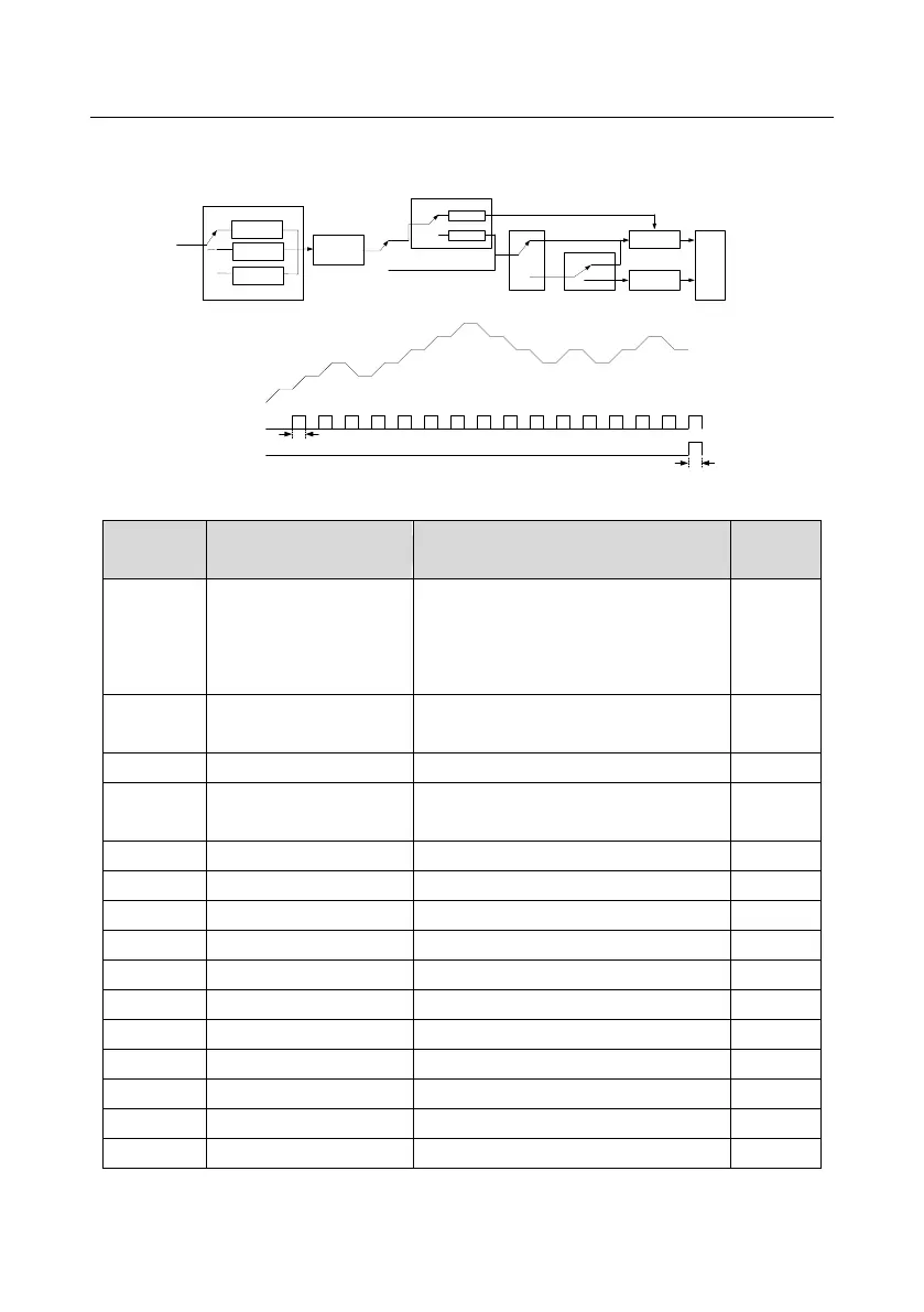
The multi-function digital output terminals or multi-function relay output an ON signal when the set
PLC finishes a circle (or a stage).
Running parameter
setting in all stages in
PLC
Restart from the first
stage
Restart form the frequency
of the pause stage
Stop after running one
time
Run at the final value
after running for one
time
Cycle
0
1
2
P10.00( simle PLC(
PLC method
0
1
0
1
0
1
Normal running
P10.01( simple PLC memory seleciton(
Power off without
memory
Power off with
memory
P10.36
( PLC starting selection (
P17.00
Power off during running
Terminal function 23
Simple PLC stop reset
Set frequency
200ms
200ms
Digital output 15
Simple PLC stage completion
Digital output 20
Simple PLC cycle completion
Relative parameters list:
Detailed instruction of parameters
0:Stop after running once
1:Run at the final value after running
once
2:Cycle running
0:Power loss without memory
1:Power loss memory
The running time of step
0
The running time of step 1
The running time of step 2
The running time of step 3
The running time of step 4
The running time of step 5

 Loading...


