Goodrive35 inverters Basic operation instruction
242
The steps of (1) ~ (4) are the same as the 4 steps in close-loop vector control mode. After the 4
steps, the control requirements can be met.
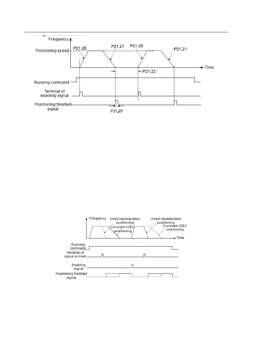
(5) Set P21.00=0011 and set P21.17, P21.11, P21.12, P21.18, P21.19, P21.20 and P21.21
according to actual needs.
(6) Single positioning operation
Set P21.16.bit1=0, and the motor will set as step (5) and keep on the positioning place.
(7) Loop positioning operation
Set P21.16.bit1=1 to enable the loop positioning which includes continuous mode and repeated
mode. The operation is also available by terminals function.
6. Photoelectric switch positioning
Photoelectric switch positioning is to position in the close loop vector control mode.
The steps of (1) ~ (4) are the same as the 4 steps in close-loop vector control mode. After the 4
steps, the control requirements can be met.
(5) Set P21.00=0021 to enable the positioning. The signal is only connected with S8. Set
P05.08=43 and P21.17, P21.11, P21.12 and P21.21. If the operation speed is big or the setting

 Loading...


