Goodrive35 inverters Installation guidelines
25
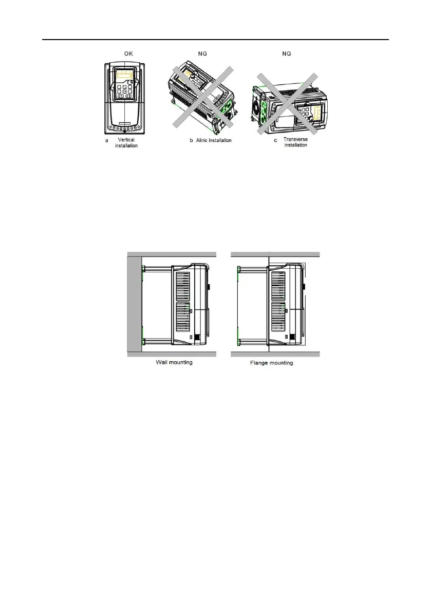
Fig 4-1 Installation direction of the inverter
4.2.3 Installation manner
The inverter can be installed in three different ways, depending on the frame size:
a) Wall mounting (for the inverters of 380V≤315kW and the inverters of 660V≤350kW)
b) Flange mounting (for the inverters of 380V≤200kW and the inverters of 660V≤220kW)
c) Floor mounting (for the inverters of 380V 220-500kW and the inverters of 660V 250~630kW)
Fig 4-2 Installation manner
(1) Mark the hole location. The location of the holes is shown in the dimension drawings in the
appendix.
(2) Fix the screws or bolts to the marked locations.
(3) Put the inverter against the wall.
(4)Tighten the screws in the wall securely.
Note: the flange installation of the inverters of 380V 1.5~30kW need flange board, while the flange
installation of the inverters of 380V 37~200kW and 660V 22~220kW does not need.
The inverters of 380V 220~315kW and 660V 250~350 kW need optional bases and there is an input
AC reactor (or DC reactor) and output AC reactor in the base.

 Loading...


