Goodrive35 inverters Appendix A
305
Example 1: Read process data of inverter
Inverter parameter selects "8: Run frequency" as PZD3 to transmit which can be achieved
by setting Pd.14 as 8. This operation is mandatory until the parameter is instead of others.
Request (From master to inverter):
Example 2: Write process data into inverter
Inverter parameter selects "2”: Traction given" from PZD3 which can be achieved by setting
Pd.03 as 2. In each request frame, parameters will use PZD3 to update until re-select a
parameter.
Request (From master to converter):
In each request frame contents of PZD3 are given by traction until re-select a parameter.
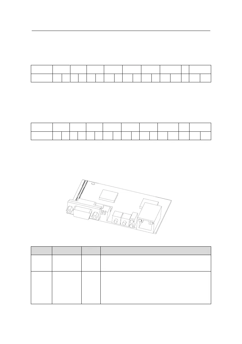
A.2.9 Fault information
EC-TX-103 communication card is equipped with 2 fault display LEDs as shown is figure
below. The roles of these LEDs are as follows:
Fault display LEDs
ON-module online and data can be exchanged.
OFF-module is not in "online" state.
ON-module offline and data can’t be exchanged.
OFF-module is not in "offline" state.
1. Flicker frequency 1Hz-configuration error: The
length of user parameter data sets is different from that

 Loading...


