Goodrive35 inverters Installation guidelines
42
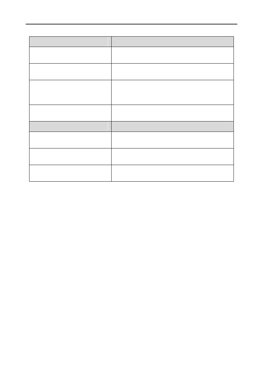
4.4.5.3 The terminal
5V differential pulse+direction reference signal,
Maximum supporting frequency 400 kHz
AO+, AO-, BO+, BO-, ZO+, ZO-
Encoder signal output, 5V differential signal and the
ratio of frequency-division is 1:1
Alarm output(If use this function, it is necessary to
short-connect Y terminal and +24V terminal, and
remove the tag between CME and COM terminal)
Common switch input (be used as running and clear
signal)
Encoder power supply, to support 5V±5%, 200mA
power
A1+, A1-, B1+, B1-, Z1+, Z1-
The encoder differential input signal, Maximum
supporting frequency 400 kHz
Difference angle input signal input of UVW encoders
(not for incremental encoders)
Note: refer to section 4.4.1 for detailed information of AO1, AO2, AI1, AI2, 485 and other
terminals.

 Loading...


