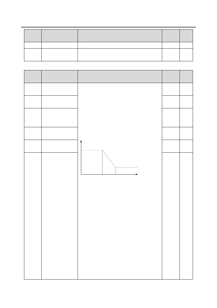
The parameters P23.00–P23.05 are applicable
only to vector control mode. Below the switching
frequency 1 (P23.02), the speed-loop PI
parameters are: P23.00 and P23.01. Above the
switching frequency 2 (P23.05), the speed-loop
PI parameters are: P23.03 and P23.04. PI
parameters are obtained according to the linear
change of two groups of parameters. See the
following figure:
The speed loop dynamic response
characteristics of vector control can be adjusted
by setting the proportional coefficient and
integral time of speed regulator. Increasing
proportional gain or reducing integral time can
accelerate dynamic response of speed loop;
however, if the proportional gain is too large or
integral time is too small, system oscillation and
overshoot may occur; if proportional gain is too
small, stable oscillation or speed offset may
occur.
PI parameters have a close relationship with the
inertia of the system. Adjust PI parameters
depending on different loads to meet various
demands.
P23.00 setting range: 0.0–200.0

 Loading...