EasyManuals Logo

INVT Goodrive270 Series User Manual

INVT Goodrive270 Series
372 pages
To Next Page IconTo Next Page
To Previous Page IconTo Previous Page
Page #253 background imageLoading...
Page #253 background image
Goodrive270 series VFD for fan and pump Function parameter list
-243-
Function
code
Name
Description
Default
Modify
1: Current
P25.41
Reserved
P26 group––Output functions of expansion I/O card
Function
code
Name
Description
Default
Modify
P26.00
Reserved
P26.01
Reserved
Same as the description for P06.01
P26.02
Y2 output
0
â—‹
P26.03
Reserved
P26.04
RO3 output
0
â—‹
P26.05
RO4 output
0
â—‹
P26.06
RO5 output
0
â—‹
P26.07
RO6 output
0
â—‹
P26.08
RO7 output
0
â—‹
P26.09
RO8 output
0
â—‹
P26.10
RO9 output
0
â—‹
P26.11
RO10 output
0
â—‹
P26.12
Expansion card
output terminal
polarity
0x0000–0x7FF
RO10, RO9…RO3, Reserved, Reserved, Y2 in
sequence
0x0000
â—‹
P26.13–
P26.14
Reserved
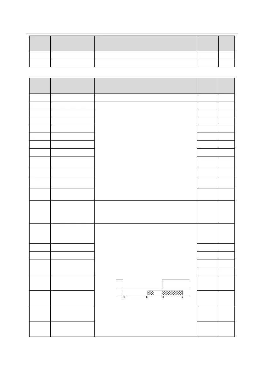
Used to specify the delay time corresponding to
the electrical level changes when the
programmable output terminals switch on or
switch off.
Y electric level
Y valid
Invalid
Switch on
delay
invalid
Valid
Switch off
delay
Setting range: 0.000–50.000s
P26.15
Y2 switch-on delay
0.000s
â—‹
P26.16
Y2 switch-off delay
0.000s
â—‹
P26.17–
P26.18
Reserved
0.000s
â—‹
P26.19
RO3 switch-on
delay
0.000s
â—‹
P26.20
RO3 switch-off
delay
0.000s
â—‹
P26.21
RO4 switch-on
delay
0.000s
â—‹
P26.22
RO4 switch-off
delay
0.000s
â—‹

Table of Contents

Questions and Answers:

Question and Answer IconNeed help?

Do you have a question about the INVT Goodrive270 Series and is the answer not in the manual?

INVT Goodrive270 Series Specifications

General IconGeneral
BrandINVT
ModelGoodrive270 Series
CategoryWater Pump
LanguageEnglish

Related product manuals