Goodrive270 series VFD for fan and pump Installation guidelines
-35-
2. Connect the ground wire of the motor cable to the PE terminal of the VFD, connect the motor 3PH
cable to the U, V and W terminals, and tighten up.
3. Fasten all the cables outside the VFD mechanically if allowed.
The screw is
not fastened.
The screw is
fastened.
YNG
Figure 4-34 Screw installation
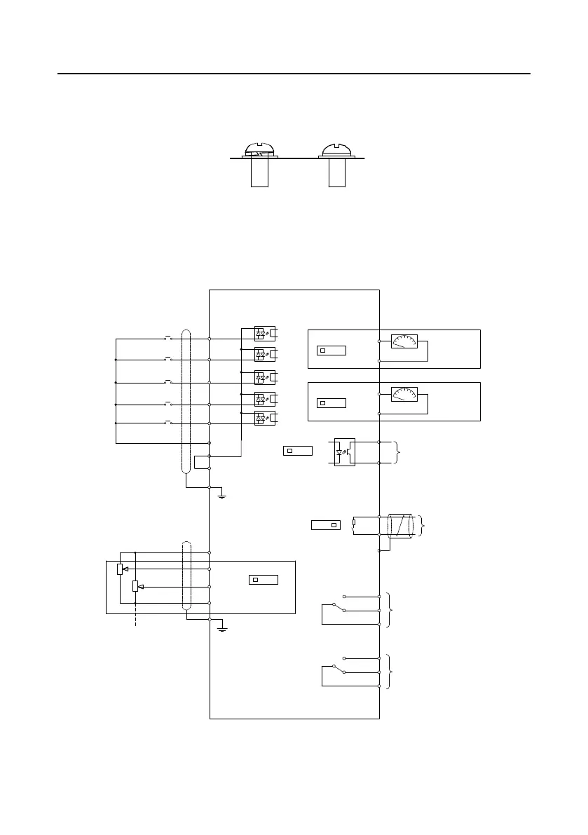
4.4 Standard wiring of the control circuit
4.4.1 Wiring diagram of basic control circuit
+24V
PE
COM
S4
S3
S2
S1
PW
HDIA
FWD run
FWD jog
Fault reset
+10V
AI1
AI2
GND
PE
-10V
(External)
VFD
AO0
V I
J7
GND
Analog output
0-10V/0-20mA
S4/Y1
COM
485+
485-
PE
RS485
communication
RO1C
RO1B
RO1A
Relay 1
output
ON
OFF
J8
Multifunction analog input
Power setting for
frequency setting
Y1
output
AO1
V I
J6
GND
Analog output
0-10V/0-20mA
V I
J11
S4 Y1
J10
RO2C
RO2B
RO2A
Relay 2
output
Figure 4-35 Control circuit wiring

 Loading...