Goodrive270 series VFD for fan and pump Function parameter list
-164-
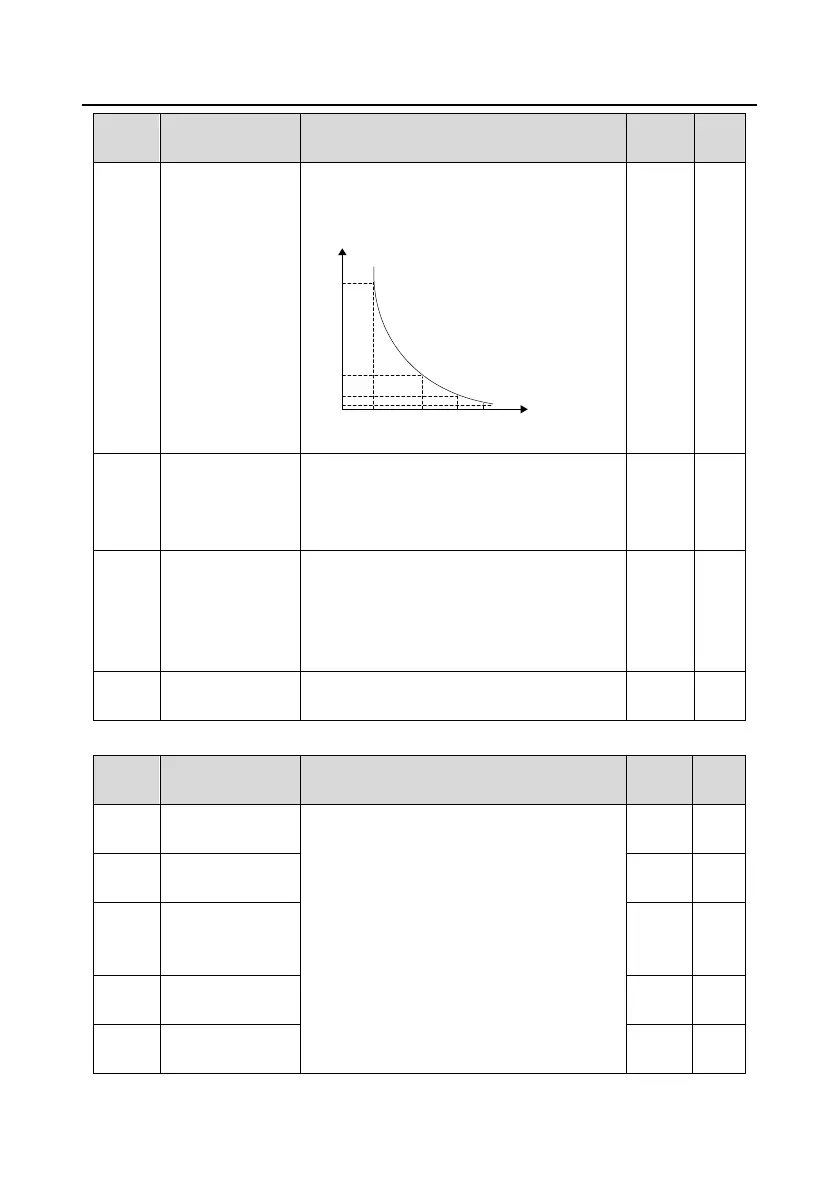
after motor overload lasts for 60 seconds; and
when M≥ 400%, protection is performed
immediately.
1
5
12
60
116%
200%
Time (min)
Current overload
multiple
150% 180%
Setting range: 20.0%–150.0%
Power display
calibration
coefficient of
motor 1
The function code can be used to adjust the
power display value of motor 1. However, it does
not affect the control performance of the VFD.
Setting range: 0.00–3.00
Parameter display
of motor 1
0: Display by motor type. In this mode, only
parameters related to the present motor type are
displayed.
1: Display all. In this mode, all the motor
parameters are displayed.
System inertia of
motor 1
P03 group––Vector control of motor 1
Speed-loop
proportional gain 1
The parameters P03.00–P03.05 are applicable
only to vector control mode. Below the switching
frequency 1 (P03.02), the speed-loop PI
parameters are: P03.00 and P03.01. Above the
switching frequency 2 (P03.05), the speed-loop
PI parameters are: P03.03 and P03.04. PI
parameters are obtained according to the linear
change of two groups of parameters. See the
following figure:
Speed-loop integral
time 1
Low-point
frequency for
switching
Speed-loop
proportional gain 2
Speed-loop integral
time 2

 Loading...