Goodrive270 series VFD for fan and pump Technical data
-331-
B.2.2.3 Derating due to carrier frequency
The carrier frequency of the VFD varies with power class. The VFD rated power is defined based on
the carrier frequency factory setting. If the carrier frequency exceeds the factory setting, the VFD
power is derated by 10% for each increased 1 kHz.
B.3 Grid specifications
According to the definition in IEC 61439-1, the maximum allowable short-circuit
current at the incoming end is 100 kA. Therefore, the VFD is applicable to
scenarios where the transmitted current in the circuit is no larger than 100 kA
when the VFD runs at the maximum rated voltage.
50/60 Hz±5%, with a maximum change rate of 20%/s
B.4 Motor connection data
Asynchronous induction motor or permanent-magnet synchronous motor
0–U1 (motor rated voltage), 3PH symmetrical, Umax (VFD rated voltage) at
the field-weakening point
The motor output short-circuit protection meets the requirements of IEC
61800-5-1.
See section 3.6 Product ratings.
1.1 times of the motor rated power
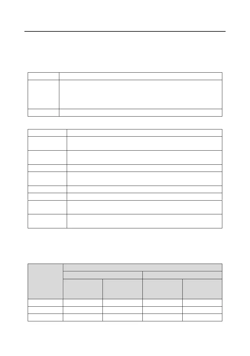
B.4.1 EMC compatibility and motor cable length
The VFD supports the built-in and external filter solutions to meet IEC/EN 61800-3 Second
environment (C3) and First environment (C2) EMC requirements. According to the 4kHz carrier
frequency setting, the motor cable length requirements are as follows:
Supported motor cable length (unit: m)
Second
environment
category C3
First environment
category C2
Second
environment
category C3
First environment
category C2

 Loading...