Goodrive270 series VFD for fan and pump Basic operation guidelines
-100-
Frequency increment
change rate of the UP
terminal
Frequency reduce rate of
the DOWN terminal
0.00Hz–P00.03(Max. output frequency)
0.00Hz–P00.03(Max. output frequency)
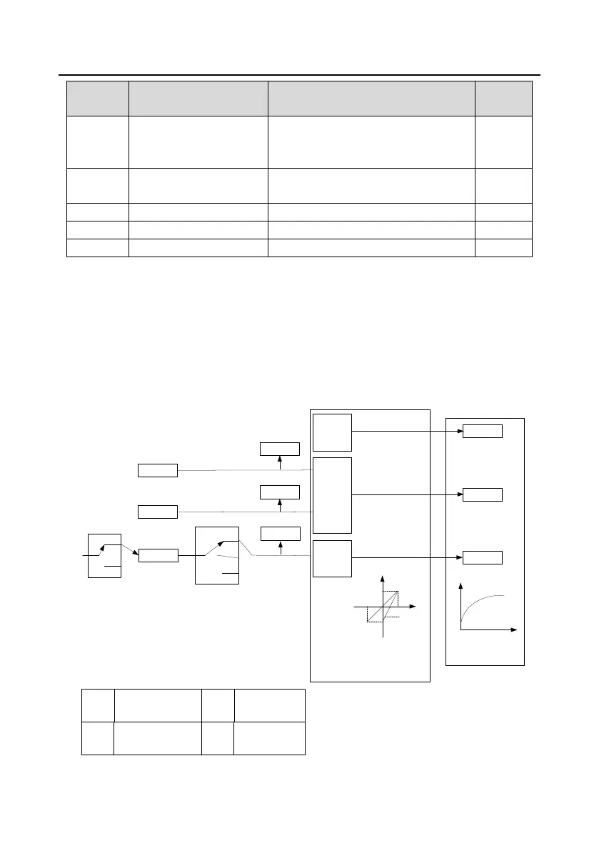
5.5.9 Analog input
The VFD carries two analog input terminals AI1 and AI2, in which AI1 supports the range of
0(2)–10V/0(4)–20mA (whether AI1 uses voltage input or current input can be set by P05.50; when AI1
uses current input, the AI-I short cap on the control board needs to be shorted) and AI2 supports the
range of -10–10V), and one high-speed pulse input terminal. Each input can be filtered separately,
and the corresponding reference curve can be set by adjusting the reference corresponds to the max.
value and min. value.
AI1
P05.24
P05.25
P05.26
P05.27
P05.39
P05.40
P05.41
P05.42
P05.43
P05.28
P17.19
AI2
P05.29
P05.30
P05.31
P05.32
P05.33
P05.34
P05.35
P05.36
P05.37
P17.20
P05.00
(HDIB input type)
P05.44
(HDIB high-speed pulse input function
selection)
AI1 input voltage
AI2 input voltage
AI1/AI2/HDI
P05.00
Ones:
0: HDIA is high-speed pulse input
1: HDIA is digital input
P05.38
0: Frequency setting
1: Reserved
2: Input via encoder
Analog input curve setting
Analog input filter
P05.00
Tens:
0: Reserved
1: Reserved
P05.44
0: Reserved
1: Reserved
2: Reserved
HDIA
P17.21
0
1
1
2
0
P05.38
(HDIA high-speed pulse input function
selection)
HDIA input frequency
P05.00
(HDIA input type)

 Loading...