Goodrive270 series VFD for fan and pump Basic operation guidelines
-102-
0–1
0: Voltage
1: Current
Note: When you set AI1 to use current
input by setting this parameter, you also
need to change the AI1 jumper cap at
the right corner of the control board
from V to I.
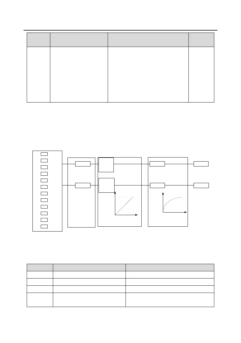
5.5.10 Analog output
The VFD carries two analog output terminals (0–10V/0–20mA) and one high-speed pulse output
terminal. Analog output signals can be filtered separately, and the proportional relation can be
adjusted by setting the max. value, min. value, and the percentage of their corresponding output.
Analog output signal can output motor speed, output frequency, output current, motor torque and
motor power at a certain proportion.
0
1
2
3
.
.
.
.
.
.
19
20
P06.14 AO1P06.21
P06.17
P06.18
P06.19
P06.20
(Default value: 0)
Analog output curve
setting
Analog output
selection
Analog output filter
P06.15
(Default value: 0)
P06.22
P06.23
P06.24
P06.25
P06.26 AO0
AO output relationship description:
(The min. value and max. value of the output correspond to 0.% and 100.00% of the pulse or analog
default output. The actual output voltage or pulse frequency corresponds to the actual percentage,
which can be set through function codes.)
0–Synchronous speed corresponding to
max. output frequency

 Loading...