Goodrive270 series VFD for fan and pump Installation guidelines
-36-
Note: If wire-passing board outlet space is insufficient when all terminals on the control board are
wired, cut the knock-out hole on the lower cover for wire outlet. If a dangerous situation occurs when
the knock-out hole is cut for a purpose but not wire outlet, we will not bear any responsibility.
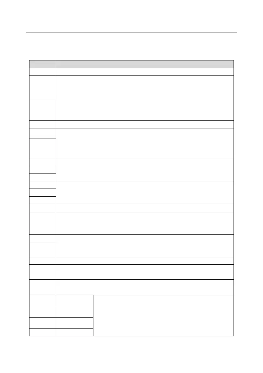
Locally provided +10.5V power supply
Input range: For AI1, 0(2)–10V or 0(4)–20mA
For AI2, -10V–+10V
Input impedance: 20kΩ for voltage input; 250Ω for current input
Whether voltage or current is used for input is set through jumper J11.
Resolution: 5mV when 10V corresponds to 50Hz
Error: ±0.5% when input is above 5V/10mA at 25°C
Output range: 0(2)–10V or 0(4)–20mA
Whether voltage or current is used for output of AO0 and AO1 is set through
jumpers J7 and J6.
Error: ±0.5% when output is 5V at 25°C
RO1 output; RO1A: NO; RO1B: NC; RO1C: common
Contact capacity: 3A/AC250V, 1A/DC30V
RO2 output; RO2A: NO; RO2B: NC; RO2C: common
Contact capacity: 3A/AC250V, 1A/DC30V
Switch capacity: 50mA/30V
Output frequency range: 0–1kHz
Y1 and S4 share the output terminal. The selection is made through J10.
RS485 communication port, RS485 differential signal port and standard RS485
communication port must use shielded twisted pairs; the 120ohm terminal
matching resistor for RS485 communication is connected through jumper J8.
Digital external power input terminal
Voltage range: 12–30V
User power supply provided by the VFD, 24V(-10%–+15%). Max. output current:
200mA
• Internal impedance: 3.3kΩ
• 12–30V voltage input is acceptable
• Bi-direction input terminal, supporting both NPN and PNP
• Max. input frequency: 1kHz
• All are programmable digital input terminals, the functions of

 Loading...