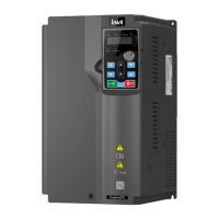
Goodrive270 series VFD for fan and pump Expansion card
-321-
Off: The expansion card is disconnected from the
control board.
On: The expansion card is powered on.
Off: The expansion card is not powered on.
EC-IO501-00 can be used in scenarios where the I/O interfaces of VFD cannot meet the application
requirements. It can provide 4 digital inputs, 1 digital output, 1 analog input, 1 analog output, and two
relay outputs. It is user-friendly, providing relay outputs through European-type screw terminals and
other inputs and outputs through spring terminals.
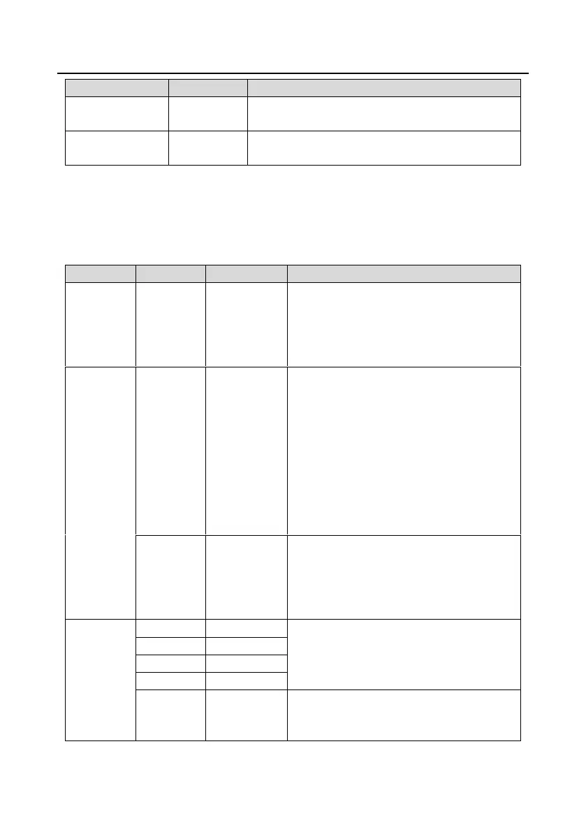
EC-IO501-00 terminal functions:
Used to provide input digital working power from
the external to the internal.
Voltage range: 12–24V
PW and +24V have been short connected before
delivery.
Input range: For AI3, 0(2)–10V or 0(4)–20mA
Input impedance: 20kΩ for voltage input;
250Ω for current input
Whether voltage or current is used for input
is set through the corresponding function
code.
Resolution: 5mV when 10V corresponds to
50Hz
Error: ±0.5% when input is above 5V or
10mA at 25°C
Output range: 0(2)–10V or 0(4)–20mA
Whether voltage or current is used for output
is set through the jumper J5
Error: ±0.5% when output is above 5 V or 10
mA at 25°C
Internal impedance: 3.3kΩ
12–30V voltage input is acceptable
Bi-direction input terminal
Max. input frequency: 1kHz
Switch capacity: 200mA/30V
Output frequency range: 0–1kHz
The terminals CME and COM are shorted

 Loading...