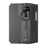
Goodrive270 series VFD for fan and pump Contents
-v-
P19 group––Expansion card status viewing ................................................................... 238
P23 group––Vector control of motor 2 ............................................................................ 239
P25 group––Input functions of expansion I/O card.......................................................... 241
P26 group––Output functions of expansion I/O card ....................................................... 243
P28 group––Master/slave control ................................................................................... 245
P89 group––HVAC status viewing .................................................................................. 246
P90 group––PID1 control ............................................................................................... 248
P91 group––PID2 control ............................................................................................... 252
P92 group––Real-time clock and timer (available at use of LCD keypad)........................ 256
P93 group––Fire control ................................................................................................. 256
P94 group––HVAC ......................................................................................................... 257
P95 group––Segmented water pressure (available at use of LCD keypad) ..................... 262
P96 group––HVAC protection ........................................................................................ 262
7 Troubleshooting ...................................................................................................................... 266
7.1 What this chapter contains .............................................................................................. 266
7.2 Indications of alarms and faults ....................................................................................... 266
7.3 Fault reset ....................................................................................................................... 266
7.4 Fault history .................................................................................................................... 266
7.5 Faults and solutions ........................................................................................................ 266
7.5.1 Faults and solutions .............................................................................................. 266
7.5.2 Other status .......................................................................................................... 273
7.6 Analysis on common faults .............................................................................................. 274
7.6.1 Motor fails to work ................................................................................................. 274
7.6.2 Motor vibrates ....................................................................................................... 275
7.6.3 Overvoltage........................................................................................................... 276
7.6.4 Undervoltage ......................................................................................................... 276
7.6.5 Motor overheating ................................................................................................. 277
7.6.6 VFD overheating ................................................................................................... 278
7.6.7 Motor stalls during ACC ......................................................................................... 279
7.6.8 Overcurrent ........................................................................................................... 280
7.7 Countermeasures on common interference ..................................................................... 280
7.7.1 Interference on meter switches and sensors .......................................................... 280
7.7.2 Interference on RS485 communication .................................................................. 282
7.7.3 Failure to stop and indicator shimmering due to motor cable coupling .................... 283
7.7.4 Leakage current and interference on RCD ............................................................. 283
7.7.5 Live device chassis ............................................................................................... 284
8 Maintenance ............................................................................................................................ 286
8.1 What this chapter contains .............................................................................................. 286
8.2 Periodical inspection ....................................................................................................... 286
8.3 Cooling fan...................................................................................................................... 289

 Loading...