Goodrive35 Series Closed-loop Vector Control VFD Function parameters
78
Detailed instruction of parameters
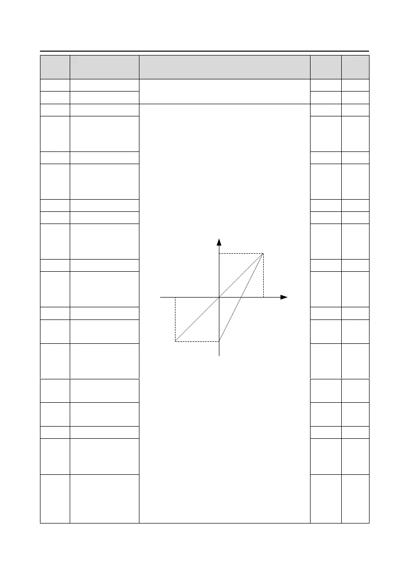
The function code defines the relationship between
the analog input voltage and its corresponding set
value. If the analog input voltage beyond the set
minimum or maximum input value, the VFD will
count at the minimum or maximum one.
When the analog input is the current input, the
corresponding voltage of 0–20mA is 0–10 V.
In different cases, the corresponding rated value of
100.0% is different. See the application for detailed
information.
The figure below illustrates different applications:
-100%
100%
Corresponding setting
AI
-10V
10V
20mA
0
AI3
AI1/AI2
Input filter time: this parameter is used to adjust the
sensitivity of the analog input. Increasing the value
properly can enhance the anti-interference of the
analog, but weaken the sensitivity of the analog
input.
Note: Analog AI1 and AI2 can support 0–10 V or
0–20mA input, when AI1 and AI2 selects 0–20mA
input, the corresponding voltage of 20mA is 5 V. AI3
can support the output of -10 V–+10 V.
The setting range of P05.32: 0.00 V–P05.34
The setting range of P05.33: -300.0%–300.0%
The setting range of P05.34: P05.32–10.00 V
The setting range of P05.35: -300.0%–300.0%
The setting range of P05.36: 0.000s–10.000s
Corresponding
setting of the lower
limit of AI1
Corresponding
setting of
the upper limit of AI1
Corresponding
setting of lower limit
of AI2
Corresponding
setting of
upper limit of AI2
Corresponding
setting of lower limit
of AI3
Zero-point deadzone
voltage of AI3
Corresponding
setting of upper limit
of AI3

 Loading...