Goodrive35 Series Closed-loop Vector Control VFD Function parameters
82
Detailed instruction of parameters
14: Set value 1 of Modbus communication
15: Set value 2 of Modbus communication
16: Set value 1 of PROFIBUS\CANopen
communication
17: Set value 2 of PROFIBUS\CANopen
communication
18: Set value 1 of Ethernet communication
19: Set value 2 of Ethernet communication
20–21: Reserved
22: Torque current (bipolar, 100% corresponds to 10
V)
23: Excitation current (100% corresponds to 10 V)
24: Setting frequency (bipolar)
25: Ramp reference frequency (bipolar)
26: Operation speed (bipolar)
27: Reserved
Lower output limit of
AO1
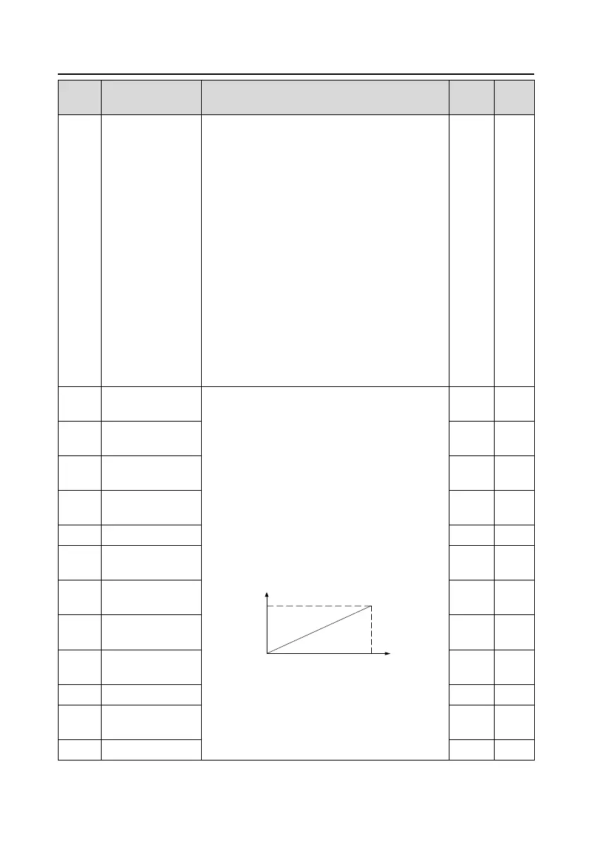
The above function codes define the relative
relationship between the output value and analog
output. When the output value exceeds the range of
set maximum or minimum output, it will count
according to the low-limit or upper-limit output.
When the analog output is current output, 1mA
equals to 0.5 V.
In different cases, the corresponding analog output
of 100% of the output value is different. See each
application for detailed information. Please refer to
section 7.10 "Analog output" for more details.
Setting range of P06.17: -300.0%–P06.19
Setting range of P06.18: 0.00 V–10.00 V
Setting range of P06.19: P06.17–300.0%
Setting range of P06.20: 0.00 V–10.00 V
Setting range of P06.21: 0.000s–10.000s
Corresponding AO1
output of lower limit
Upper output limit of
AO1
Corresponding AO1
output of upper limit
Lower output limit of
AO2
Corresponding AO2
output of lower limit
Upper output limit of
AO2
Corresponding AO2
output of upper limit
Lower output limit of
HDO

 Loading...