Goodrive35 Series Closed-loop Vector Control VFD Function parameters
89
Detailed instruction of parameters
P08 Group Enhanced function
For detailed definition, see the description of P00.11
and P00.12.
Four groups of ACC and DEC time are defined for
the Goodrive35 series. You can set the ACC and
DEC time through the corresponding multi-function
digital input terminals (in the P05 group). For the
Goodrive35 series VFD, the default setting is the first
group of ACC and DEC time.
Setting range: 0.0–3600.0s
This parameter is used to set the reference
frequency of the VFD during jogging.
Setting range: 0.00 Hz–P00.03 (max. output
frequency)
P08.07 indicates the time the VFD takes to
accelerate from 0 Hz to P00.03 (max. output
frequency).
P08.08 indicates the time the VFD takes to
decelerate from P00.03 (max. output frequency) to 0
Hz.
Setting range: 0.0–3600.0s
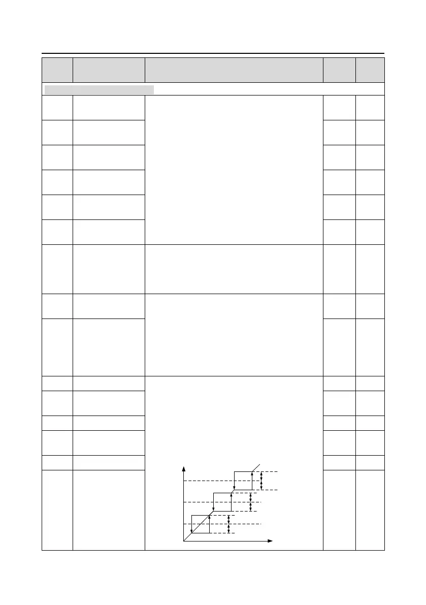
When the set frequency is in the range of jumping
frequency, the VFD will run at the edge of the
jumping frequency.
The VFD can avoid the mechanical resonance point
by setting the jumping frequency. The VFD can set
three jumping frequency. But this function will be
invalid if all jumping points are 0.
Set frequency f
Time t
Jump
frequency 2
1/2* jump amplitude 2
1/2* jump amplitude 2
Jump
frequency 1
1/2* jump amplitude 1
1/2* jump amplitude 1
Jump
frequency 3
1/2* jump amplitude 3
1/2* jump amplitude 3
Jumping frequency
range 1
Jumping frequency
range 2
Jumping frequency
range 3
 Loading...
