Goodrive35 Series Closed-loop Vector Control VFD Function parameters
90
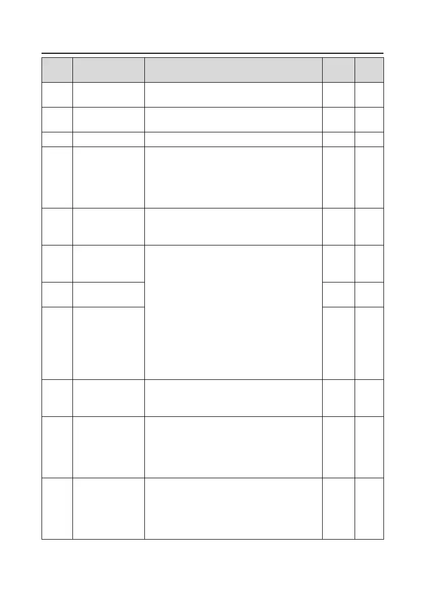
Detailed instruction of parameters
Setting range: 0.00 Hz–P00.03 (max. output
frequency)
Overvoltage stall
modulator gain
Setting range: 0.0–1000.0
Setting range: 0.00–10.00s
Max torque of inertia
compensation
Limit the max. inertia compensation torque to
prevent the inertia compensation torque from being
too large.
Setting range: 0.0–150.0% (rated torque of the
motor)
Inertia compensation
filter times
Filter times of inertia compensation torque is used to
smooth the inertia compensation torque.
Setting range: 0–10
High-frequency ACR
proportional
coefficient
In the closed-loop vector control mode (P00.00=3),
when the running frequency is lower than the ACR
high frequency switching point (P08.21), the ACR PI
parameters are P03.09 and P03.10; and when the
running frequency is higher than the ACR high
frequency switching point, the ACR PI parameters
are P08.19 and P08.20.
Setting range of P08.19: 0–20000
Setting range of P08.20: 0–20000
Setting range of P08.21: 0.0–100.0% (relative max
frequency)
High-frequency ACR
integral coefficient
ACR high frequency
switching point
Inertia identification
torque
Because of the friction, it is necessary to set
identification torque for normal inertia identification.
0.0–100.0% (rated torque of the motor)
0: No operation
1: Starting identification: press "RUN" to enter into
the program after starting identification until display
"-END-"; the identified system inertia is saved in
P08.24.
The identified system inertia can be set manually
when the system inertia is known. The displayed
system inertia may be less than 0.001kgm
2
for the
motors below 1 kW.
Setting range: 0.000–30.000 kgm
2
 Loading...
