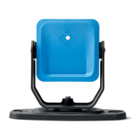
Note: install the sensor so that the field of view is tilted towards the outside of the hazardous area to avoid false
alarms (see"Position of the field of view" on page55).
Installation on the machinery.
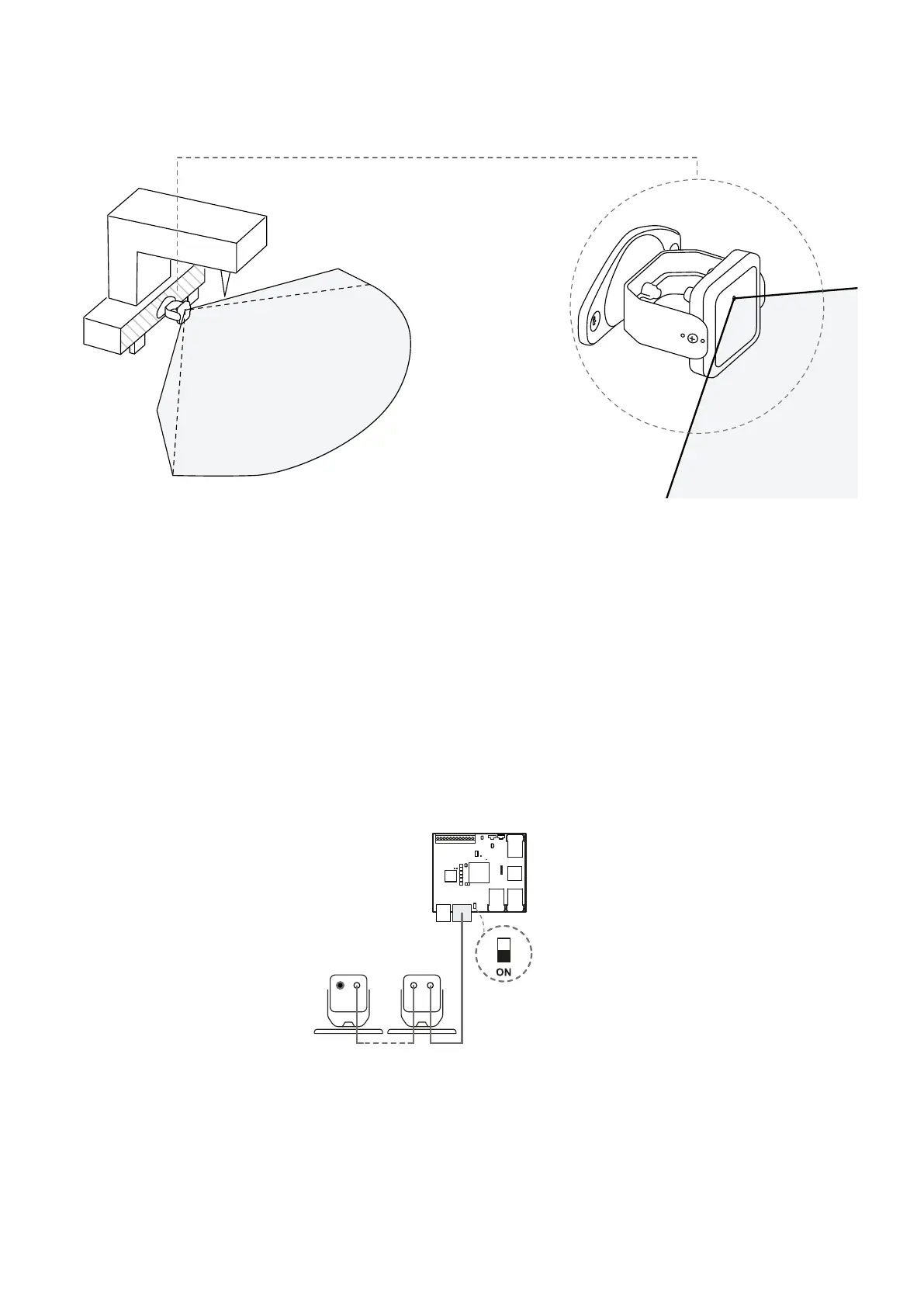
8.2.6 Connect the sensors to the control unit
Note: the total maximum length of the CAN bus line is 80 m (262.5 ft).
Note: when replacing a sensor, in the Inxpect Safety application, click APPLY CHANGES to confirm the change.
1. With the cable validator tool (downloadable from the site https://tools.inxpect.com), decide if the
control unit will be positioned at the end of the chain or inside it (see "Chain examples" below).
2. Set the DIP switch of the control unit based on its position in the chain.
3. Connect the desired sensor directly to the control unit.
4. To connect another sensor, connect it to the last sensor in the chain or directly to the control unit to
start a second chain.
5. Repeat step 4 for all the sensors to be installed.
6. Insert the bus terminator (product code: 07000003), into the free connector of the last sensor of the
chain(s).
8.2.7 Chain examples
Chain with control unit at the end of the chain and a sensor with bus terminator
8. Installation and use procedures
Inxpect SRE 200 Series | Instruction manual v1.5 DEC 2023|Inxpect SAF-IM-200S_5m_7_00047_en_v1.5|© 2021-2023 Inxpect SpA
71