Inspection and Installation
2. Remove the cover of output terminal and remote sense terminal.
3. Connect the L+ and SL+, N- and SN- for short circuit using the short clips on
the back panel of the instrument or electric wire. When using local sense,
the remote sense terminal cannot be disconnected.
4. Loosen the screws of the output terminals and connect the red and black
test cables to the output terminals, and connect the ground terminal cor-
rectly. Re-tighten the screws.
5. Thread the red and black test cables through the output terminals cover of
the instrument and install the cover.
6. Directly connect the other end of the red and black cables to the DUT.
Connecting the DUT (Remote Sensing)
When the DUT consumes large current or the wires are too long, there is a volt-
age drop on the wires between the DUT and output terminal of the power sup-
ply. To maximize measurement accuracy, you can use remote sense wire
connections to monitor and improve the voltage adjustment on the DUT and
compensate for the voltage drop on the wires .
When the power supply is used for measuring battery charge in actual applica-
tions, the voltage drop of the wire will lead to voltage inconsistency of both ends
and inconsistency of the cutoff voltage of power supply and the actual voltage of
battery, resulting in inaccurate measurement.
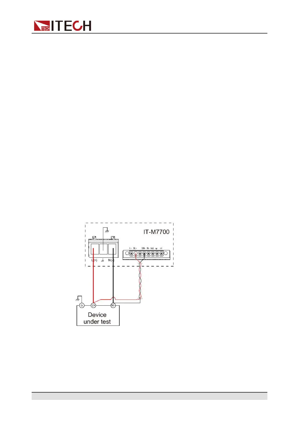
The connection diagram and steps of remote sensing are as follows:
1. Confirm that the power switch is in the Off position
2. Remove the cover of output terminal and remote sense terminal.
3. Disconnect the wires/short clips between SL+ and L+, SN- and N-.
4. Use armored twisted-pair cables to connect the remote sense terminals and
the device under test.
Copyright © Itech Electronic Co., Ltd.
28
 Loading...