Inspection and Installation
5. Loosen the screws of the output terminals and connect the red and black
test cables to the output terminals, and connect the ground terminal cor-
rectly. Re-tighten the screws.
6. Install the terminal cover, leave the other end of remote sense cables and
the red and black cables outside.
7. Connect the other end of the remote sense cables and the red and black ca-
bles to the DUT.
Test lines and sense lines should be as short as possible, and sense lines
should be twisted together.
2.5 Connecting the Interface
The IT-M7700 series power supply has no standard-equipped interfaces card.
Users can purchase interface cards separately. Users can choose one of RS-
232, RS-485, USB, GPIB, LAN, CAN to communicate with the computer. For
details, see 1.8 Optional Accessories
The reserved interface card installation slot is on the rear panel of the instru-
ment. Users can install it directly after purchasing the interface card. Hot swap
is not available for the interface card. After changing the interface card, you
must re-start the instrument.
The installing steps for the purchased interface card are as follows:
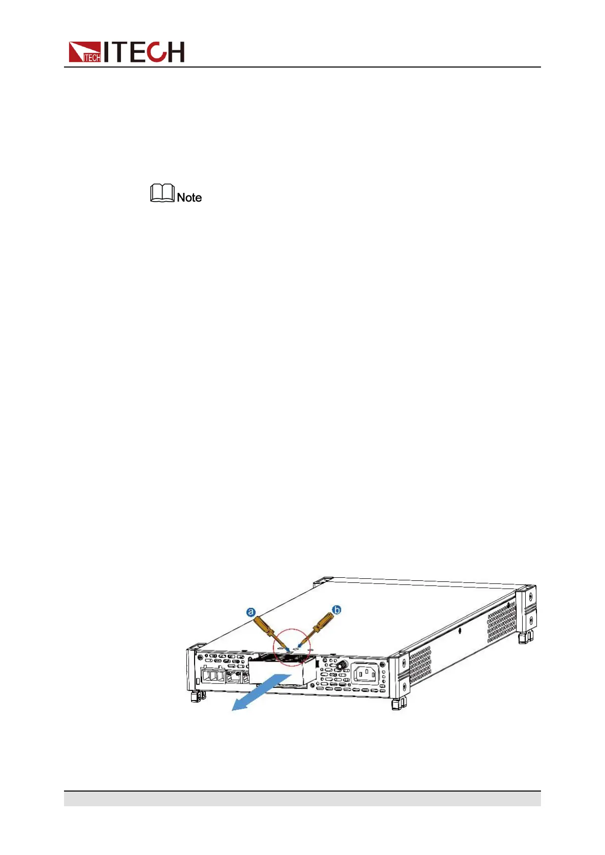
1. Remove the plug of the rear panel interface.
a. Use a small flat screwdriver to press the clip at the upper cover opening.
b. At the same time, use another small flat screwdriver to stir the slots one
by one from another opening of the upper cover, and push the plastic
plug out.
2. Install the purchased communication card. Taking the LAN+USB interface
card as an example, push the card into the slot and secure with the screws
Copyright © Itech Electronic Co., Ltd.
29
 Loading...