Operation and Application
Monitor and Clear Error Status
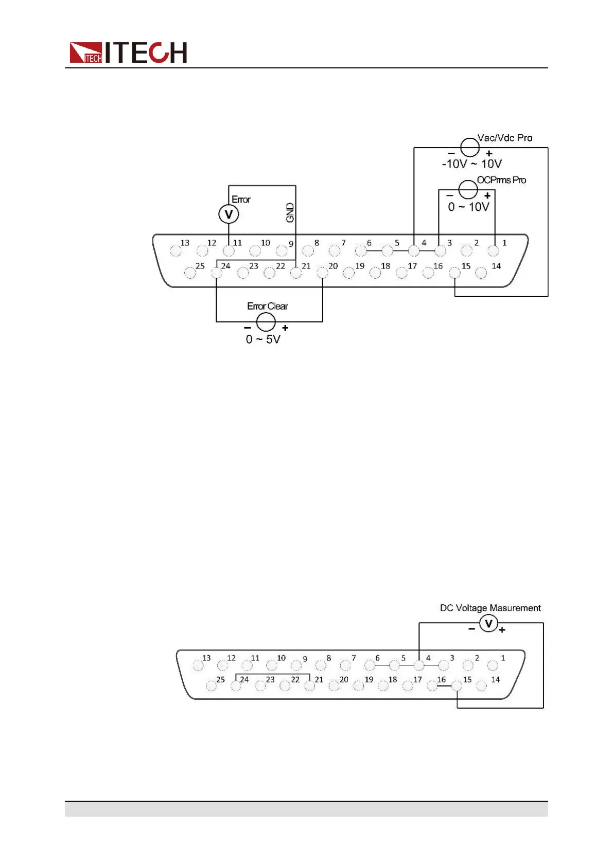
This function can monitor and clear the instrument error status. The connection
diagram is as follows:
• Monitor instrument error status: if the instrument occurs error status (Over
OVPrms or OVPpeakor UVPrms or OCPrmsor OCPpeak or Over tempera-
ture or Fan Error), Pin 11 will output 5V; if the instrument is in a non-error
status, Pin 11 will output 0V.
• Clear instrument error status: when Ext In Edge = Hi/Act, if Pin 20 input is
from 0V to 5V, the error status indicated by Pin 11 will be cleared; when Ext
In Edge = Lo/Act, if Pin 20 input is from 5V to 0V, the error status indicated
by Pin 11 will be cleared.
4.12.4 Calibrate external voltage control
The method of external voltage control calibration is as follows.
1. Please refer to the figure below for connection of the instrument under
calibration.
By connecting a digital voltmeter to the 15, 16 and 6 pins.
2. Enter calibration mode.
a. Press the composite keys [Shift] + [DC](System) to enter into the system
menu interface.
Copyright © Itech Electronic Co., Ltd.
94
 Loading...