Inspection and Installation
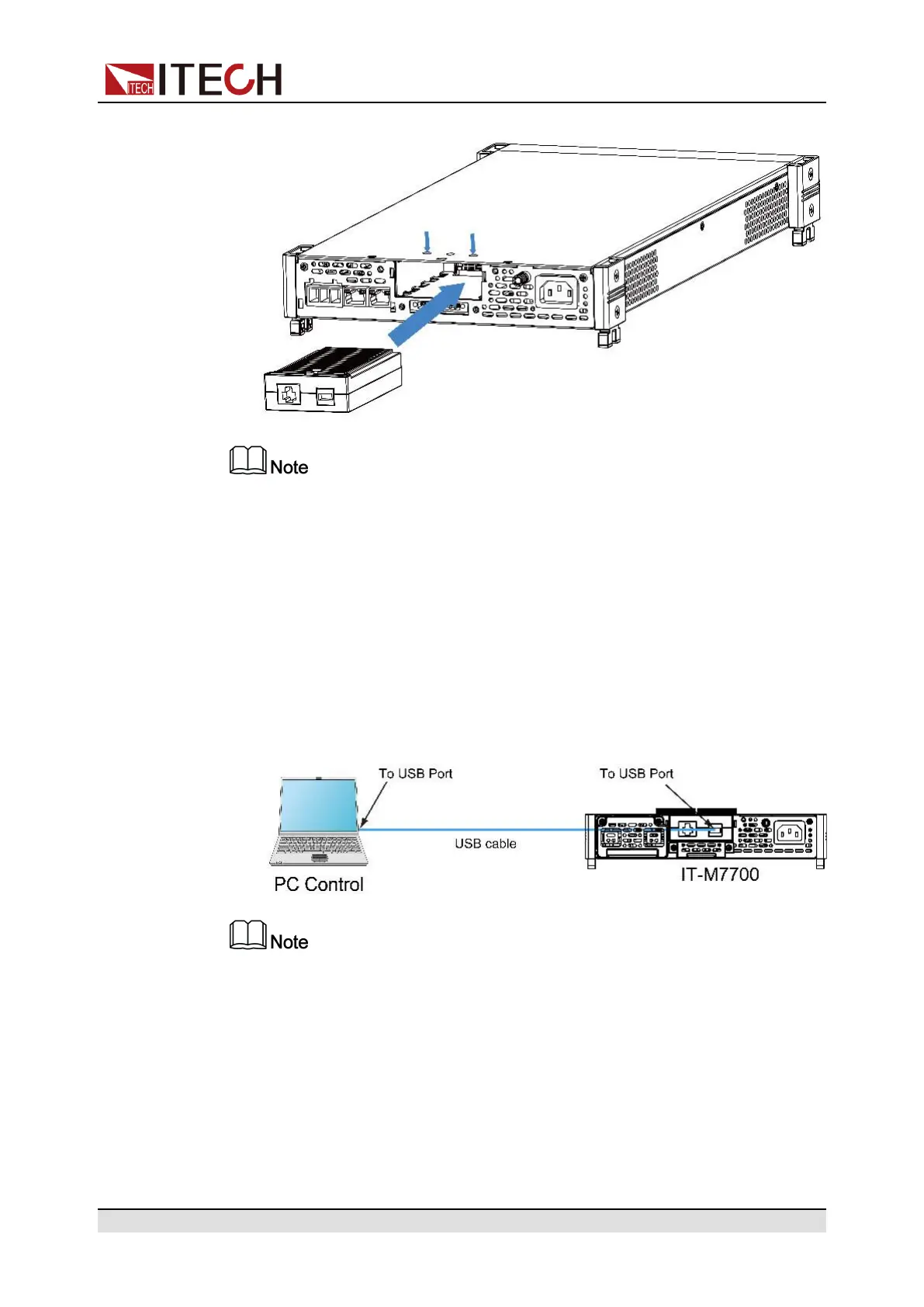
from the upper cover, it is shown as follow.
Firstly loosen the screws between upper cover and communication card and
removing the communication card like removing the plug, please use the
tools and remove it.
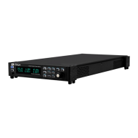
2.5.1 USB Interface
When the optional interface card is a stand-alone USB interface (IT-E1209) or
USB+LAN interface (IT-E1206), the following can help users quickly understand
the steps required to connect the USB interface. The figure below shows a typi-
cal USB interface system.
Take the IT-E1209 communication card box as an example. If you install IT-
E1206, please refer to the actual interface position.
The operation steps to use the USB interface are as follows.
1. Refer to the USB connection diagram, Connect the power supply and the
computer using a cable with two USB interfaces (each end).
2. Press the composite keys [Shift] + [DC](System) to enter into the system
menu interface.
3. Rotate the knob to select I/O Config and press [Enter] key to confirm.
Copyright © Itech Electronic Co., Ltd.
30