Inspection and Installation
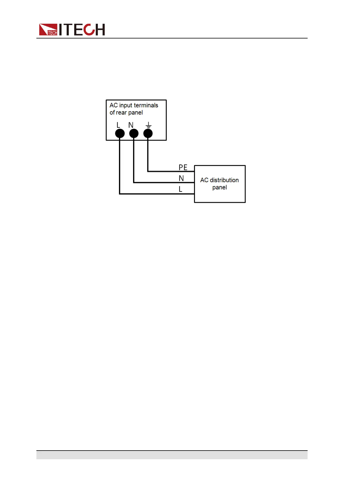
1. See the below illustration, one end of the AC power cord is connected to
the AC input terminal in the rear board of the power supply. Connect the
fire wire, zero line and ground to the corresponding terminal of the
device.
2. Connect the three terminals brown to line (L), blue to neutral (N), and yel-
low-green to ground (PE) on the other end of the power cord to your AC
distribution panel.
2.4 Connecting the Device Under Test (DUT)
The instrument supports two connection methods between power supply and
DUT: Local measurement and Remote sensing.
• Local measurement:The voltage sensed by the instrument is the voltage at
the output terminal of the instrument.
• Remote sensing:The voltage sensed by the instrument is the voltage at the
terminal of the remote object under test.
Precautions
To prevent electric shock and damage to the instrument, observe the following
precautions.
Copyright © Itech Electronic Co., Ltd.
26