Operation and Application
• Voltage monitoring: Output current values can be monitored and read by
connecting a digital voltmeter to the 16 and 5 pins.
By connecting a digital voltmeter to the Vrms/Vdc Monitor or Irms/Idc Monitor
pins, a voltage reading from 0 to + 10 V corresponds to the zero to full-scale
voltage or current output of the power supply.
For example, if the maximum rated value is 300 V, and if the pin 16 generates
2.5 V, the output voltage should be approximately 75 V. If the maximum rated
value is 6 A, and if the pin 14 generates 1 V, the output current should be ap-
proximately 0.6 A.
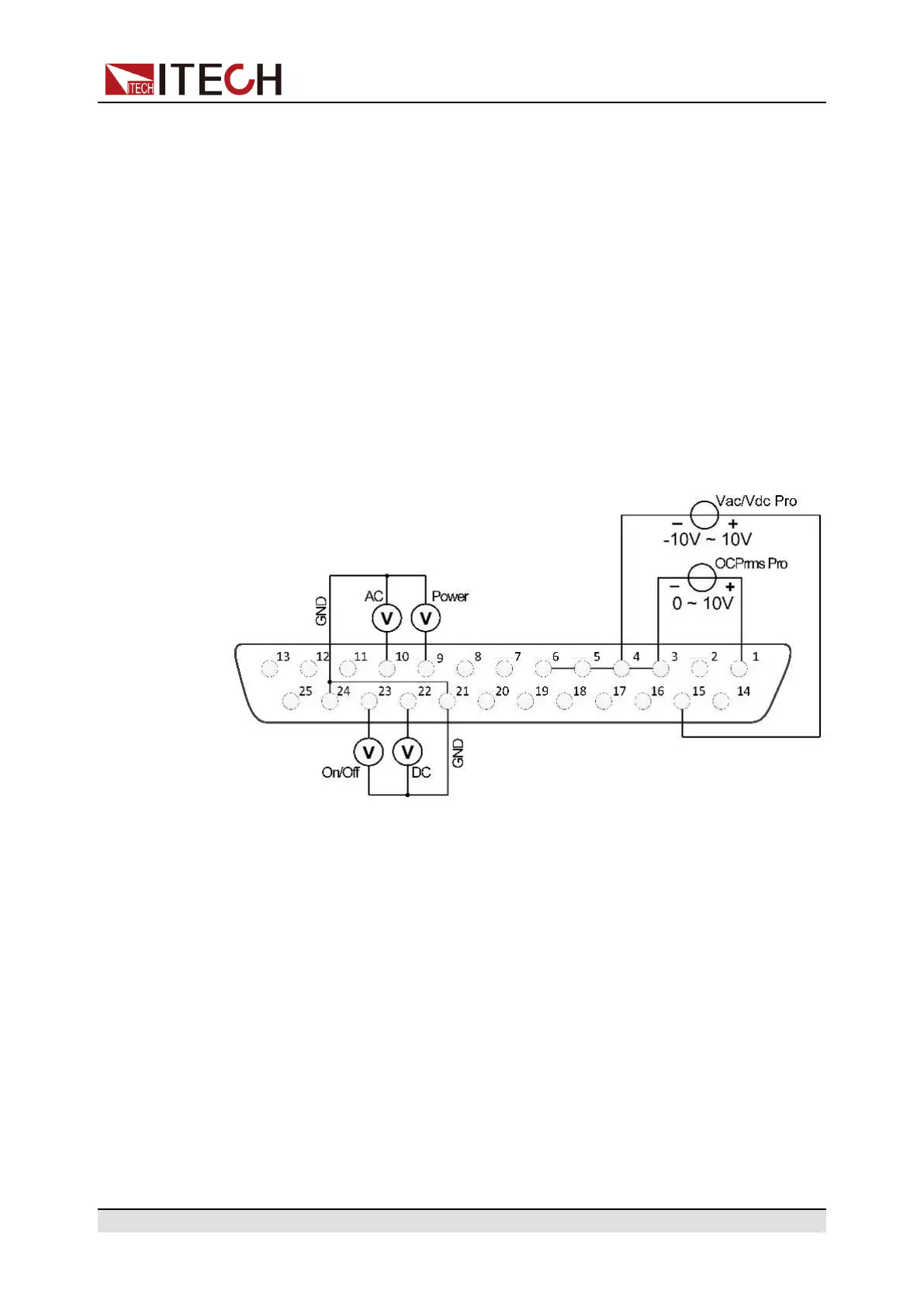
Monitoring of output status
You can connect a standard multi-meter to a pin with appropriate status to moni-
tor the output mode, loaded status and On/Off status of the instrument. The con-
nection diagram is as follows:
• Monitor the AC output mode: When Pin 10 outputs 5V, it indicates that the
instrument is in the AC mode; otherwise, Pin 10 will output 0V.
• Monitor the DC output mode: When Pin 22 outputs 5V, it indicates that the
instrument is in the DC mode; otherwise, Pin 22 will output 0V.
• Monitor the instrument load status: If the instrument is under normal loading
status, Pin 9 will output 5V; if the instrument is in unloaded status, Pin 9 will
output 0V.
• Monitor the instrument On/Off status: When the instrument is On, Pin 23 will
output 5V; when the instrument is Off, Pin 23 will output 0V.
Copyright © Itech Electronic Co., Ltd.
93
 Loading...