Operation and Application
• L To out on: When send 0V signal to IO2, the instrument turns on the
output. When send 5V signal to IO2, the instrument turns off the
output.
• H To out on: When send 5V signal to IO2, the instrument turns on
the output. When send 0V signal to IO2, the instrument turns off the
output.
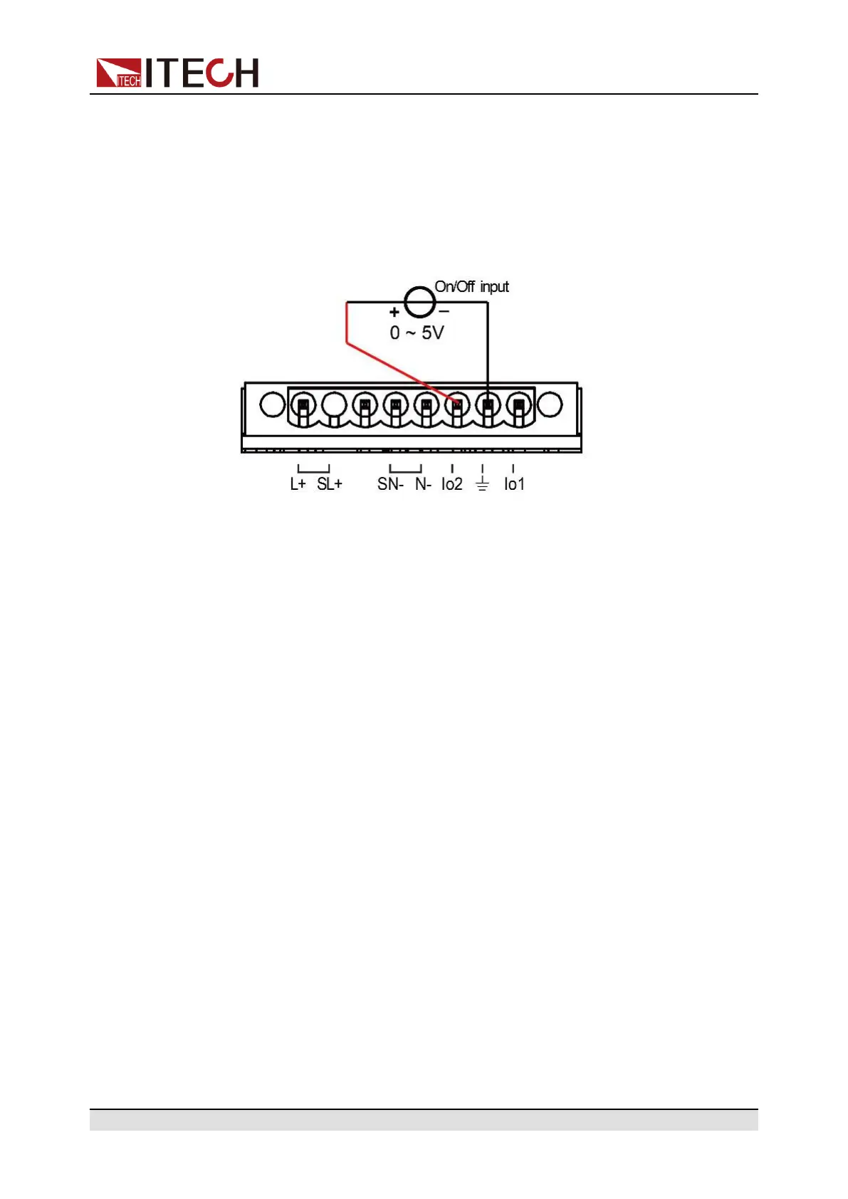
2. There is an external DC voltage source capable of outputting 0V ~ 5V volt-
age between IO2 and GND to control power output.
Monitoring of output status
You can connect a standard multi-meter to IO1 and IO2 to monitor the On/Off
status of the instrument. The operation steps are as follows:
1. Config IO1 as output pin.
a. Press the composite keys [Shift] + [I-set](Function) to enter function
menu interface.
b. Rotate the knob to select Ext IO1 and press [Enter] key to confirm.
c. Rotate the knob to select Output and press [Enter] key to config IO1 as
output pin.
d. Rotate the knob to select L if out on or H if out on and press [Enter]
key to confirm.
• L if out on: When the output state of the instrument is On, this pin
outputs 0V. When the output state of the instrument is Off, this pin
outputs 5V.
• H if out on: When the output state of the instrument is On, this pin
outputs 5V. When the output state of the instrument is Off, this pin
outputs 0V.
2. You can connect a digital voltmeter to IO1 and GND to monitor the On/Off
status of the instrument.
Copyright © Itech Electronic Co., Ltd.
70
 Loading...