System-Related Functions
Copyright ©ITECH Electronic Co., Ltd. 116
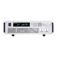
4. Connect the AC input terminals of the three units separately, and connect
them to the AC distribution box.
5. Connect the output terminals of the three units in parallel and connect them
to the DUT.
6. Refer to the blue wiring legend in the figure, connect the System Bus (i.e.,
the fiber outer ring interfaces TX and RX) for fiber-optic communication
between the master and slaves.
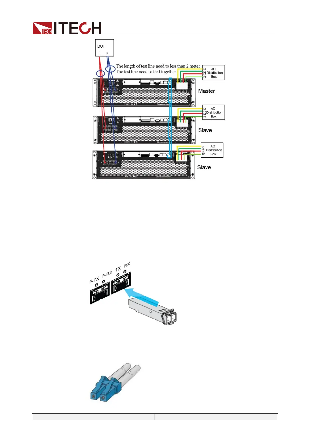
a) Insert the fiber optic module into the hole corresponding to TX RX.
b) Insert the plug of the fiber optic cable into the fiber optic module and hear a
click sound to indicate that it is inserted in place. The fiber optic cable
connection schematic is as follows.
 Loading...