JA-101K(-LAN)(-LAN3G) and JA-106K(-3G)
Security System Control Panels 24 / 110 MLJ51410
5.9 Power supply requirements
The control panel requires to be powered permanently by 230 V or 110 V protected AC power, see the chapter
17 Technical specifications. The control panel is a device with double isolation so its connection is usually
performed by a cable with double insulation and a cross-section of 0.75 to 1.5 mm². The control panel has
a protective small glass fuse. It is a part of the mains power terminals. The producer doesn´t recommend you
to power the control panel from alternative sources such as high-capacity batteries charged by solar panel, etc.
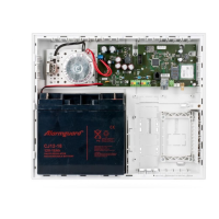
5.10 Backup requirements
A security system which has to comply with security grade 2 has to backed up by backup battery for 12 hrs
during a mains power disconnection and it also has to be fully charged 72 hrs after mains power recovery
and be ready to back the system up again To comply with this requirement it is necessary to ensure that
the backup battery capacity is adequate for the required time, see the following example.
Calculation of maximum permanent current taken from system BUS according to the backup battery capacity:
JA-106K control panel, for 18 Ah battery (calculation is valid for 80% of battery capacity)
18 Ah * 0.8 / 12 h = 1.2 A (according to the capacity - maximum current for 12 hrs)
Imax = 1.2 A – 0.09 A = 1.1 A (subtract the control panel self-current 0.09 A)
JA-101K control panel, for 2.6 Ah battery (calculation is valid for 80% of battery capacity)
2.6 Ah * 0.8 / 12 h = 0.17 A (according to the capacity - maximum current for 12 hrs)
Imax = 0.17 A – 0.05 A = 0.12 A (subtract the control panel self-current 0.05 A)
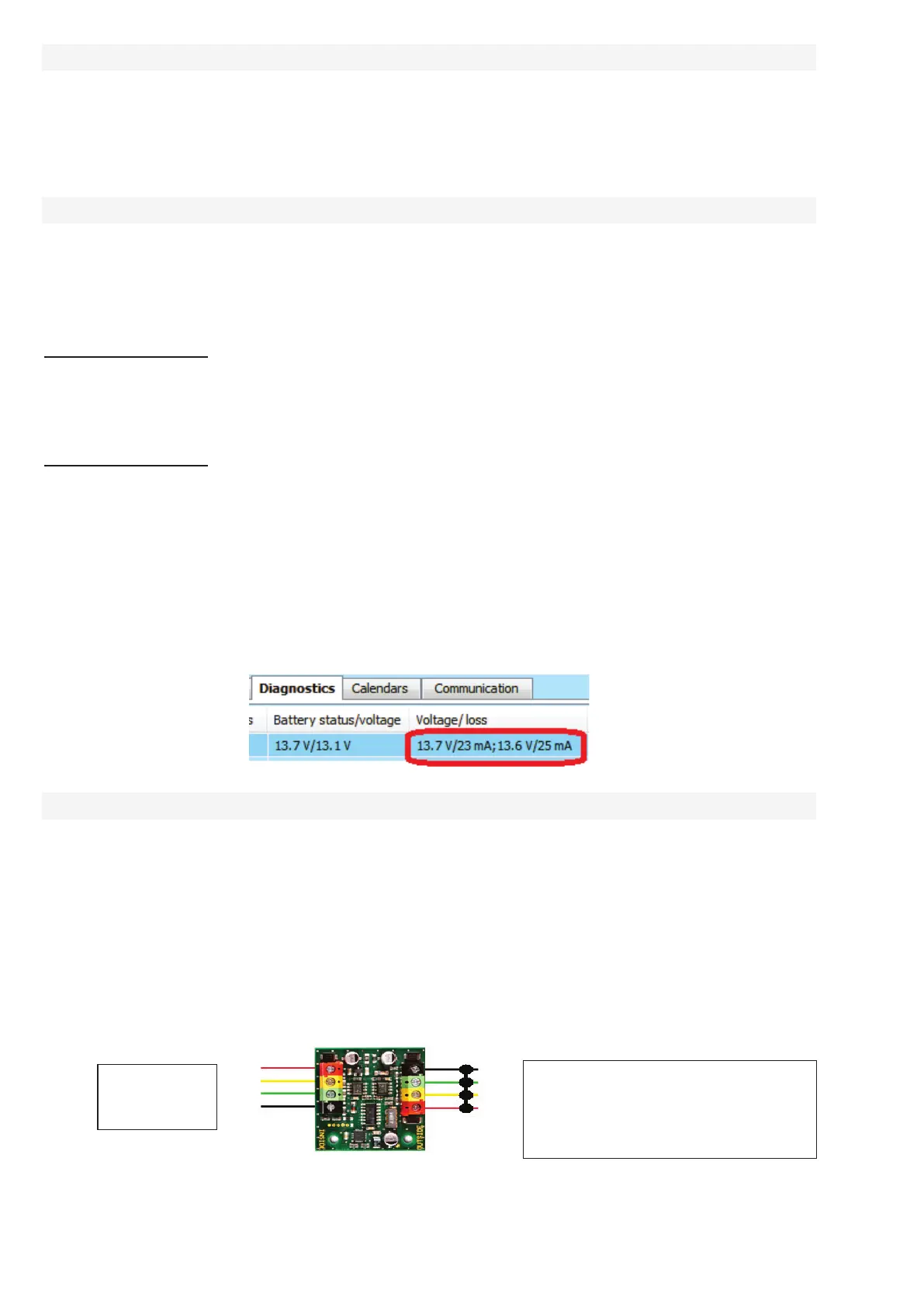
The current taken from each BUS output terminal is shown in the F-Link SW in the Diagnostics tab on line
0 where the control panel is. It is necessary to take consideration of the shown current (for the JA-106K control
panel it is necessary to sum the values of both BUS output terminals) especially when the JA-11xR module
is used (wireless control panel) connected to the special RJ connector so also add the current of this module.
This current is compared with a calculated current and it determines if the backup battery capacity is adequate
to norm requirements for system backup time. If the measured current is higher than the calculated one,
the backup battery should have a bigger capacity.
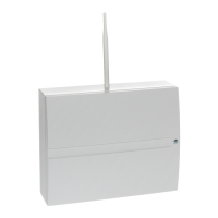
5.11 BUS isolation
Parts of the BUS routed in unprotected areas must be protected from possible short-circuit or another attempt
to disable the system by isolation using a JA110T BUS isolator. This module can be incorporated in a JA-190PL
multipurpose installation box. The isolator also improves the signal quality of the BUS. It is connected to and
powered by the BUS, it does not occupy any position in system and makes it possible to extend (1x)
the maximum BUS length up to next 500 m. Avoid using 2 or more BUS isolators on one BUS leg –devices
cannot communicate through them.
An application example may be routing of the BUS to relay modules controlling for example blinds or a siren
to which the BUS is routed in such a way that it could be potentially attacked or disabled from outside.
You will find more information in the JA-110T manual.
BUS from
control panel
Possible BUS damaging behind the
module caused for instance by short
circuit, doesn´t influence the BUS in
front of the module!