JABLOTRON ALARMS a.s.
Pod Skalkou 4567/33 46601 Jablonec n. Nisou
Czech Republic www.jablotron.com
||
|
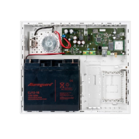
JA-101K(-LAN)(-LAN3G) and JA-106K(-3G)
Security System Control Panels 91 / 110 MLJ51410
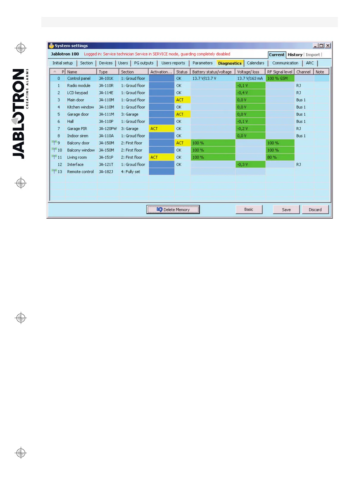
10.13 Diagnostics tab
It is used to check and verify the status of devices and their properties.
* Items marked this way are displayed if Advanced Settings are on.
Activation memory – registers activations of the device that have occurred since the last deletion of this
column. The memory of all devices activations can be deleted with the Delete memory button (bottom bar).
You can delete the memory of a selected device using the right mouse button. Activation of a tamper sensor
(TMP) has the highest priority when events are recorded in the memory.
Status – indicates the current status of the device. OK = everything all right, TMP = tampering, ACT = alarm
input activated, ERR = error, ?? = no communication with the device, Mains supply = supply failure
(or completely discharged battery), Charging – charging the backup battery in the device or control panel.
Battery = discharged or disconnected battery in the control panel, BOOT – upgrading of the device is going
on or upgrade failure (repeat upgrade). By moving the mouse cursor on the STATUS of the respective device
you will display details.
Battery* – If the device contains a battery, its status is displayed. For the control panel (position 0) the voltage
of the backup battery is displayed. If the voltage data of a wireless device are missing, the device
has not communicated yet – activating its transmission (e.g. by means of the tamper sensor
or in F-Link click on the Load button) or wait until automatic transmission occurs. If wireless keypads are
powered by an external power supply source “Powered from external source” is indicated. For wireless devices
(except devices of the JA-18x series) battery status is visible. Colour coding of the battery status: 10% red, 20%
yellow, 30% and higher green.
Voltage* – On the position of the control panel (0) voltage of the control panel terminals and current that
is drawn by the BUS devices from the control panel are displayed (individually for each BUS output). For BUS
device the line voltage loss as compared to the control panel is displayed. The loss must not be higher than 2 V;
otherwise the problem must be solved.
RF signal level* – indicates quality of the signal with which the control panel communicates in GSM
or wireless device RF. The value should be at least 50%. If the indication is missing, the device
has not communicated yet – activated its transmission (e.g. by means of the tamper sensor) or wait until
automatic transmission occurs. The value on the control panel line is the strength of the GSM network signal
(about the interference between radio modules and the GSM module see also chapter 6.1 Installation
of a JA-11xR radio module).
Colour coding of the GSM signal: 0-30% red, 40-50% yellow and over 50% green.
Colour coding of the RF signal: 10% red, 20% yellow, 30% and higher green.