10
JAKA Zu MiniCab v1.1
Chapter 2 Welcome
Before reading this chapter, make sure that you have read and fully understood the Safety Specifications
in Chapter 1.
This chapter will provide a quick introduction to JAKA Zu MiniCab's basic components and usage as a
preliminary understanding of the robot. For detailed mechanical and electrical specifications and software
operation manual, please refer to other chapters.
If you need immediate help when using the MiniCab, please call our quick enquiry hotline: 400-006-2665.
2.1 Typical Application Schematic Diagram
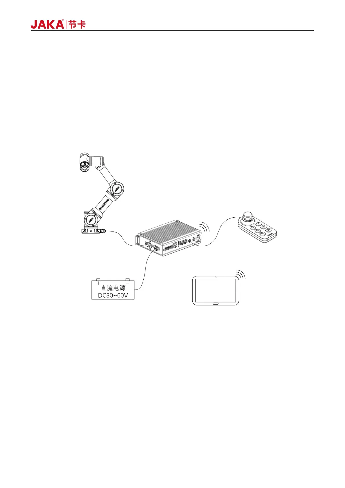
Figure 2-1 Typical MiniCab Application
As shown in Figure 2-1, the JAKA Zu MiniCab controller adopts the mode of wireless interconnection and
integrates the function of Wi-Fi hotspot internally. It needs to include the following parts when in use:
Operation Terminal: The device for users to perform programming, setting, and other operations.
Robot Body: Main moving parts to achieve the desired action of the user. At the same time, the robot end
is equipped with a ring indicator light indicating the status of the robot, buttons for dragging and programming,
and an I/O interface for connecting tools, namely the TIO interface.
Operation Handle: The controller is equipped with user-friendly handle to control robot operation and
emergency stop operation.
DC Power: The controller adopts DC voltage input, supports DC 30-60V wide voltage range, and can use
48V battery or DC module power supply as input source.