24
JAKA Zu MiniCab v1.1
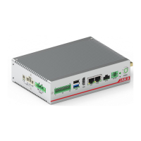
5.2 Side-panel Interface
Figure 5-5 Diagram of Side Panel
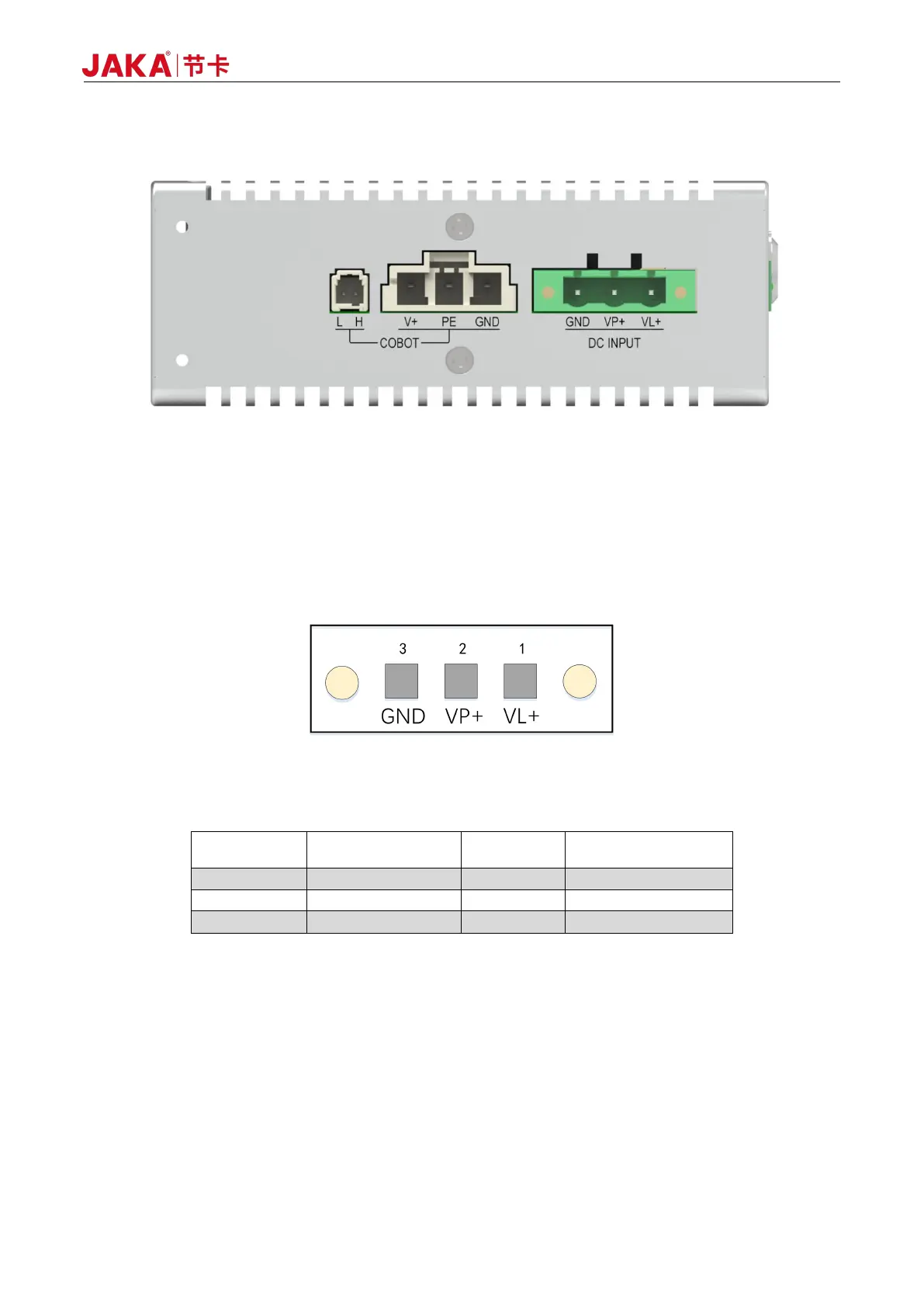
5.2.1 Power Interface
The power interface is divided into two power circuits: logic power VL+ is the pin of the internal logic power
supply of the controller; power VP+ is the power supply voltage of the robot arm; meanwhile, VP+ can also
supply the internal logic power supply. Interface definitions are as follows:
Figure 5-6 Diagram of Power Interface
Table 5-5 Pin Definitions of Power Interface
The robot power supply input can supply power for the robot body, and can also supply power for the logic
circuit in the electric control cabinet. When the logic power supply and robot power supply do not need to be
separated, just connect pin 2 and pin 3; In order to meet the current carrying capacity, it is recommended to
use cable14AWG or 1.63mm
2
and above .
5.2.2 Robot Interface
The COBOT port is the terminal of the robot body. Both terminals support the function of anti-freeze latch.
JAKA provides adaptive cables.