22
JAKA Zu MiniCab v1.1
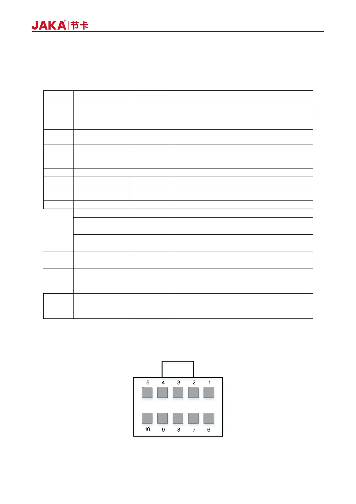
The user integration interface uses a double row of 3.5mm pluggable terminal to integrate rich interfaces
for users.
The specific interface pins are defined as follows:
Table 5-2 Pin Definition of Integrated Interface
Integrated interface 24V power output, internal
integrated 2.7A overcurrent protection function
Common terminal of user interface power, default
external short connect to PIN1
Integrated interface 24V power output, same as
PIN1
User interface power logic ground
Remote shutdown control input, connecting to 24V to
trigger shutdown operation
User interface power logic ground, same as PIN4
I/O multiplexing terminal channel 4, NPN type
Remote startup control input, connecting to the
external +24V power to trigger startup operation
I/O multiplexing terminal channel 3, NPN type
I/O multiplexing terminal channel 7, NPN type
I/O multiplexing terminal channel 2, NPN type
I/O multiplexing terminal channel 6, NPN type
I/O multiplexing terminal channel 1, NPN type
I/O multiplexing terminal channel 5, NPN type
For internal debugging only
RS485, master station interface
Usually used to extend the RS485 interface
of I/O board card
RS485, slave station interface
Usually used for external PLC and other
equipment communication
5.1.2 Handle Interface (STICK)
Figure 5-3 Diagram of Handle Interface