JAKA Zu MiniCab v1.1 23
MiniCab handle interface is defined as follows
(1)
,
Table 5-3 Definition of Handle Interface
3.3V logic signal input, low level trigger
controller switch operation
Handle and controller communication CAN
signal
Handle and controller communication CAN
signal
Connected to pin 1 internally (24V)
24V logic input, high level indicates that
emergency stop is normal.
Connected to pin 1 internally (24V)
24V logic input, high level indicates that
emergency stop is normal.
Note:
(1) Only used to connect JAKA Zu BP handle. External interface cannot be modified arbitrarily.
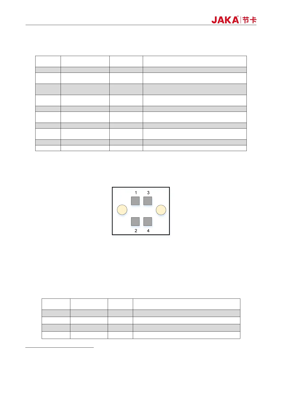
5.1.3 Emergency Stop Interface (E-STOP)
Figure 5-4 Diagram of E-STOP Interface
The external E-STOP input interface adopts double rows of 3.5mm spacing interchangeable wiring
terminals. In case of external emergency stop, the Pin1, Pin2, Pin3 and Pin4 shall be short-connected by wires.
The factory-default setting is short connection. Interface definitions are as follows:
Table 5-4 Pin Definitions of E-STOP Interface
Internal logic power 24V output
E-STOP input 1, default short connected to PIN1
Internal logic power 24V output
E-STOP input 2, default short connected to PIN3