JAKA Zu MiniCab v1.1 29
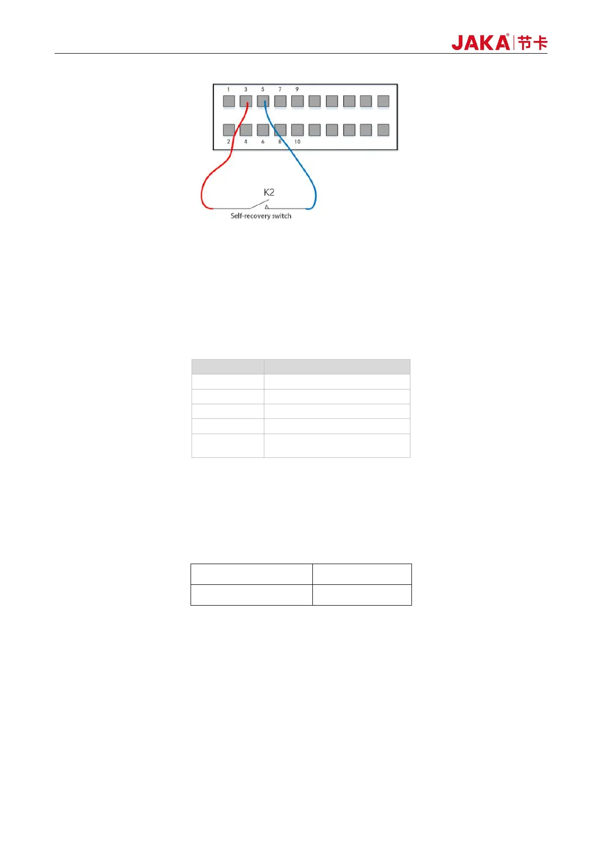
Figure 6-7 Remote_OFF - Using External Power Source
6.2.4 LED State Indicator
For the JAKA Zu Cobot, the status indicator light is equipped on the handle and the panel. The color of the
light reflects the status of the robot. The following is the connection between the LED light and status.
Table 6-3 LED Status Indicator
6.2.5 Integrated UDIO
The integration interface has 7 channels of IO, and each channel of UDIO_x has the function of NPN input
and NPN output. Users can select each channel separately in the host computer of the APP.
1. DI |Digital Input:
When configured as DI, it is an NPN type input, and will be effective when UDIO_1(PIN13) is
short-connected to GND(PIN6). When using internal UDIO_24V, short connect PIN1 and PIN2 by default. The
typical wiring diagram is as follows: