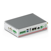
JAKA Zu MiniCab v1.1 25
Chapter 6 Detailed Introduction
6.1 Overview
JAKA Zu MiniCab is optimized for integrated applications, with a special focus on ease of use when
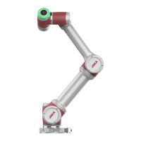
integrated into user devices. It can be used and integrated with JAKA Zu® series robot.
6.2 Function Application
This section is mainly used to guide users to use JAKA Zu MiniCab to control the robot so that the
customers can use this controller more easily. At the same time, it involves the knowledge of robot use. Please
refer to the specific robot user manual in detail.
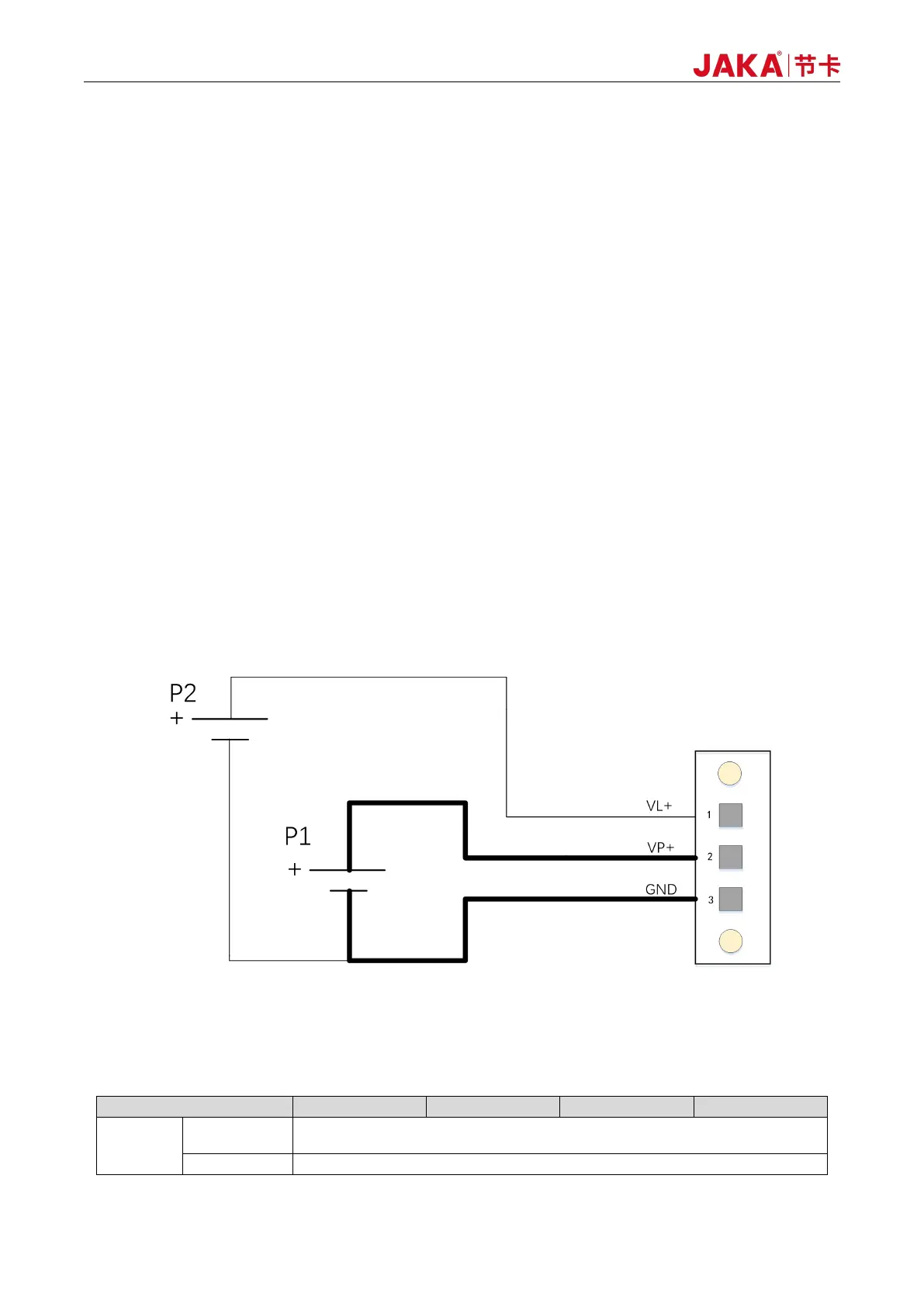
6.2.1 Electrical Service Requirements
MiniCab power interface includes three input terminals: robot logic power supply input VL+(Pin1), robot
body power supply input VP+(Pin2) and common negative GND(Pin3).
The VP+ and VL+ inputs are supplied to the MiniCab logic circuit via diodes. So you usually just need to
plug in VP+ and GND externally.
If it is necessary to disconnect VP+ in case of emergency and if you do not want to disconnect the
controller logically, the logic power can be separately connected at VL+.
FIG. 6-1 Diagram of Power Supply Wiring
1、 The power P1 (motive power) required for different models is shown in the table below:
Table 6-1 Description of Motive Power Requirements