JAKA Zu MiniCab v1.1 19
Chapter 4 Electric Parameters
4.1 Introduction
This chapter mainly describes the absolute limit parameters of MiniCab and the recommended conditions
of use. When using the robot and MiniCab controller, users shall follow the recommended electric parameters,
and reaching or exceeding the limit parameters may cause damage to the controller hardware.
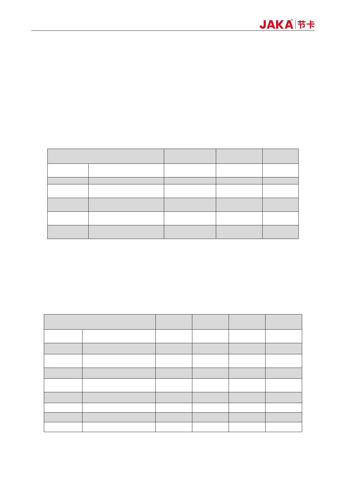
4.2 Absolute Limit Parameter
Table 4-1 Electric Limit Parameters
Logic power supply
voltage
Integration interface
common terminal voltage
Integration interface output
current
Integration interface single
channel output current
RS485 bus withstand
voltage
Note:
(1) Exceeding the values listed in the "Absolute Limit Parameters" may cause permanent damage to the equipment. These represent
limits and it is not recommended that the functional operation of the device be performed under these conditions or any other conditions
other than the "Recommended Operating Conditions".
(2) All voltage values except bus voltage are related to the grounding.
4.3 Recommended Usage Conditions
Table 4-2 Recommended Operating Conditions
Logic power supply
voltage
User interface single
channel output current
Note: