SM-18006
4-33
MAINTENANCE
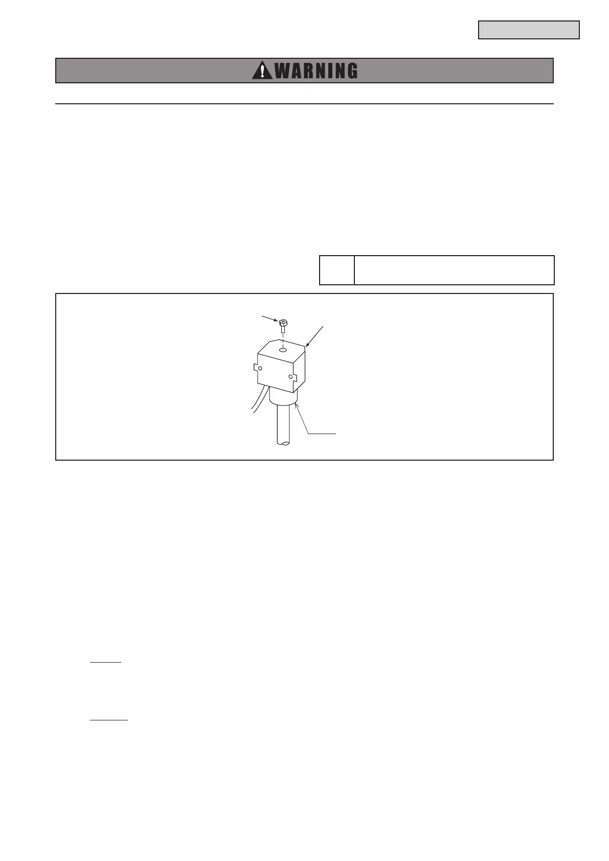
4.1.12.2 RemovingSolenoidValveCoil(SVA,SVB,SVC,SVG)
(1) Remove the service cover and front cover according to Section 4.1.1 “Removing Service Cover and
Front Cover”.
(2) Remove the upper cover according to Section 4.1.3 “Removing Upper Cover”.
(3) Remove the rear cover according to Section 4.1.4 “Removing Rear Cover”.
(4) Remove the side cover R according to Section 4.1.6 “Removing Side Cover”.
(5) RemovetheelectricalboxaccordingtoSection4.1.8“RemovingElectricalBox”.
(6) Removeonescrewsecuringthesolenoidvalvecoilwithaphillipsscrewdriver.Ifthescrewisdifcult
toremove,useanadjustablewrenchoraratchet.
(7) Remove the solenoid valve coil.
TURN OFF all POWER supply switches.
Solenoid V
Solenoid Valve Coil
4.1.12.3 RemovingSolenoidValveBody(SVA,SVB,SVC,SVG)
(1) Remove the service cover and front cover according to Section 4.1.1 “Removing Service Cover and
Front Cover”.
(2) Remove the upper cover according to Section 4.1.3 “Removing Upper Cover”.
(3) Remove the rear cover according to Section 4.1.4 “Removing Rear Cover”.
(4) Remove the side cover R according to Section 4.1.6 “Removing Side Cover”.
(5) RemovetheelectricalboxaccordingtoSection4.1.8“RemovingElectricalBox”.
(6) Closethehigh/lowpressuregasstopvalve,lowpressuregasstopvalve(onlyforheatrecovery
system)andtheliquidstopvalve.
(7) Collecttherefrigerantinthewatersourceunitfromthelowpressureaccessportandthehighpressure
access port. Check that the pressure does not increase at this time.
NOTE:
Ifthepressureincreases,collectalltherefrigerantintherefrigerantcycle.
(8) Remove the solenoid valve coils according to Section 4.1.12.2 “Removing Solenoid Valve Coil”.
(9) Removethebrazingatthepositionshowninthegureonnextpage.
NOTES:
● Duringbrazingwork,coverthesolenoidvalvebodywithwetclothforcooling.
● Takespecialcarenottoburntheconnectingwiringandthepipinginsulationduringbrazingwork.
(10) Reassemblethesolenoidvalvesinthereverseprocedure.
Tool
PhillipsScrewdriver,
AdjustableWrenchorRatchet



 To Next Page