SM-18006
3-43
TROUBLESHOOTING
3.2.2 Troubleshooting Using Alarm Codes
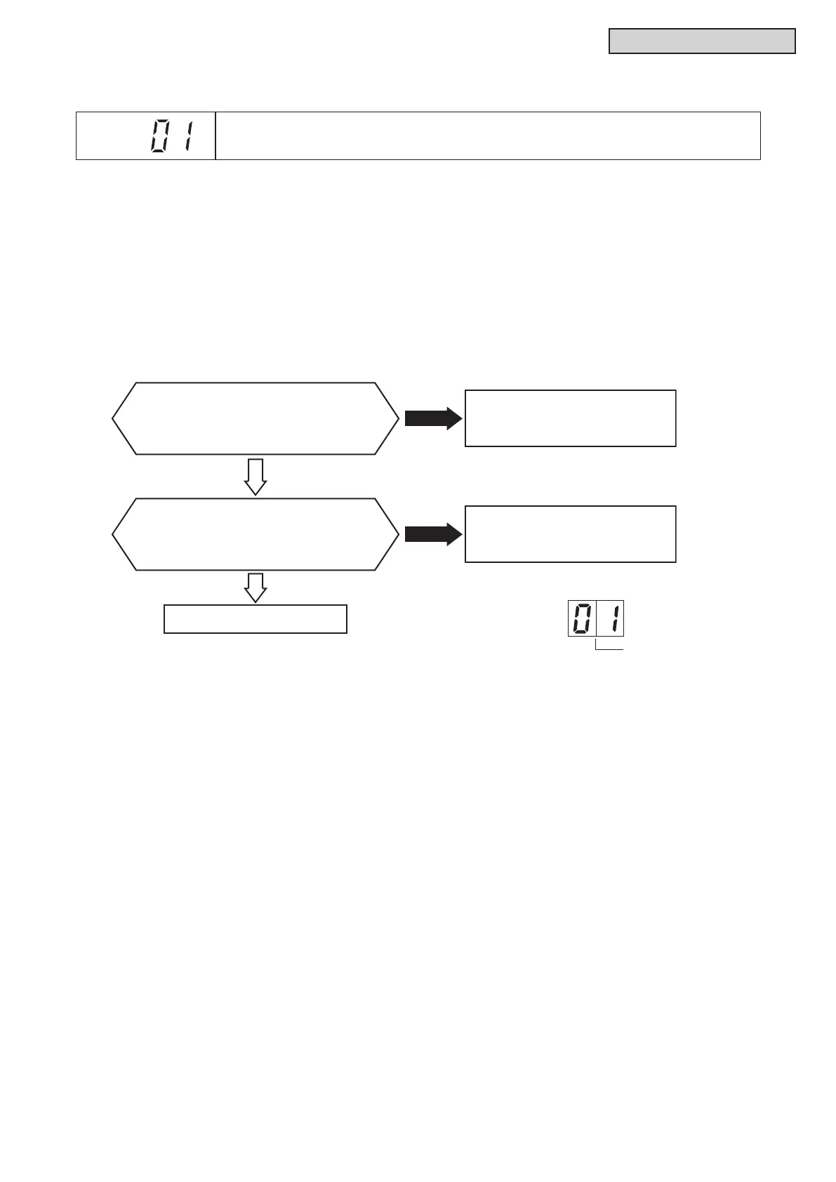
Alarm
Code
Activation of Protection Device (Float Switch) in Indoor Unit
l
TheRUNindicator(red)ashes.
l
The indoor unit number (Ref. system number - I.U. number), the alarm code, the model code
1
, the
model name
1
and the number of connected indoor units are displayed on the LCD. The indoor unit
numberandalarmcodeareashedonthe7-segmentdisplayofthewatersourceunitPCB.
Note 1: Except for some models.
(Example of 4-way Cassette Type)
This alarm code is displayed when the contact between #1 and #2 of CN14 on the I.U. PCB is opened for
over 120 seconds during the cooling, dry, fan, or heating operation.
I.U. PCB: Indoor Unit PCB
Turn OFF power supply and remove
connectors CN36 and CN14 on I.U. PCB.
Then turn ON power supply. Is DC12.5~
13.5V applied between CN36 terminals?
Turn OFF power supply and attach
connector CN14 on I.U. PCB. Then
turn ON power supply. Is voltage applied
between CN36 terminals less than 12.5V?
Failure of I.U. PCB
Failure of Drain Pump
Activation of Float Switch FS
or Failure of Float Switch.
Yes
Make sure short circuit does not occur between CN36 terminals
when measuring the voltage. Short circuit will lead to I.U. PCB
malfunction.
Yes
No
No
Indication on Water Source Unit PCB (SEG1)
Alarm Code