SM-18006
3-27
TROUBLESHOOTING
3.1.6 Checking Alarm Code History
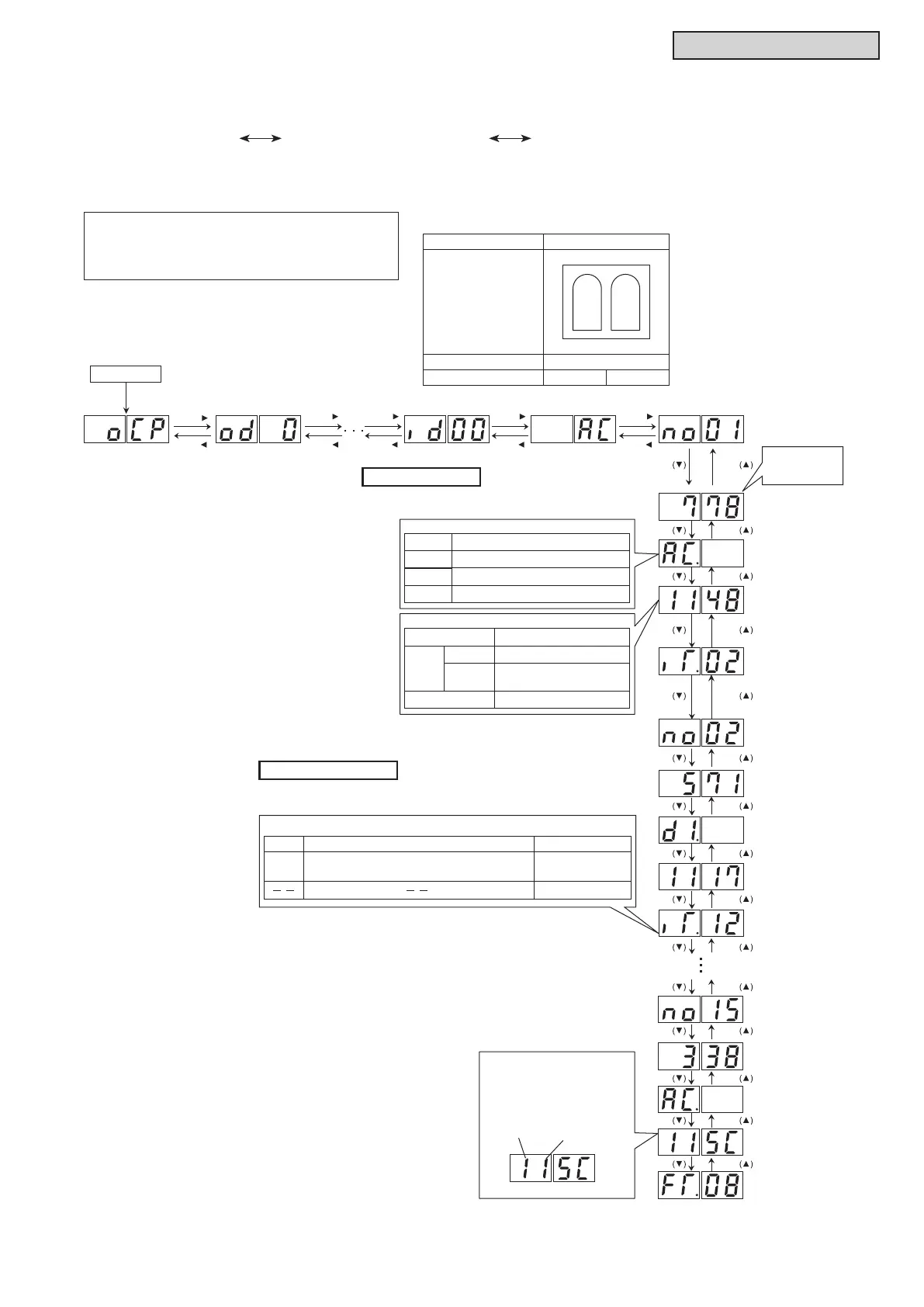
Alarm code history is indicated in the following order while the Check Mode is displayed.
“no01” (latest)
history data ~ “no15” (oldest) history data
Refer to the gure below as an example.
Alarm code history displays a maximum
of 15 alarms in order of occurrence.
Normal Mode
Press PSW1
more than 3 seconds.
PSW3( )
Accumulated
Time When
Alarm Occurs.
The activation of overload protection at No.1 compressor
of the water source unit B (No.1 Unit) is indicated.
Alarm History No.
Operation
Stoppage Code
Retry Code
Inverter Stoppage
Code (iT)
Example of Alarm
The earth fault detection by No.1 inverter PCB
of the water source unit B (No.1 Unit) is indicated.
Example of Inverter Retry
Alarm/Retry Code
Compressor/Inverter PCB
and Thermistor
Alarm/Retry Code
Indication of Stoppage Code
PSW5( )
PSW3( )
PSW5( )
PSW3( )
PSW5( )
PSW3( )
PSW5( )
PSW3( )
PSW5( )
AC.
d1.
Ci.
SEG2
SEG1
iT.
SEG2 SEG1
PSW4 PSW2
PSW4 PSW2
PSW4 PSW2
PSW4 PSW2
PSW4 PSW2
PSW4 PSW2
PSW4 PSW2
PSW4 PSW2
PSW4 PSW2
PSW4 PSW2
PSW4 PSW2
PSW4 PSW2
PSW4 PSW2
PSW4 PSW2
PSW4 PSW2
Indication of Stoppage Code
Item
Item
Item
Contents
Contents
Contents
Alarm Code
Retry Stoppage
Micro Computer Reset
Unit Digit
Tens Digit
Water Source Unit No.
Remarks
iTC
(Cause Code of Inverter Stoppage)
In case of iTC
Other than above
7-Segment Display Contents
Supplement Information
Abnormal Code
Comp. No.
INV PCB No.
Thermistor Code
Water Source
Unit No.
Water Source Unit A
Subject compressor when alarm/retry code is displayed.
(Example: (H,Y)VWHR216B(3,4)2S)
1
Combination of
Compressor
Water Source Unit No.
Compressor No.
0
2
INV.
Comp.
INV.
Comp.



 To Next Page