5-4
SM-18006
EXTERNAL INPUT/OUTPUT AND FUNCTION SETTING
The following functions have been already set at the factory.
< Input >
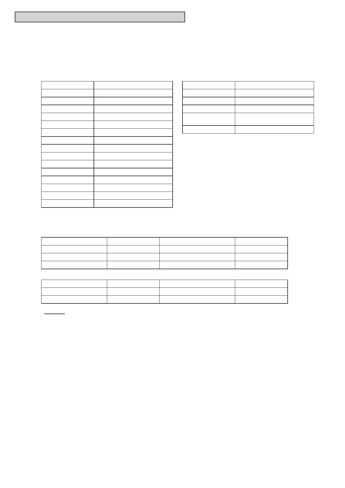
Control Function No. Setting Function for Input
1 FixingHeatingOperationMode
2 FixingCoolingOpeationMode
3 Demand Stoppage
4 Flow Switch Signal
5 Forced Stoppage
6 Demand Current Control 40%
7 Demand Current Control 60%
8 Demand Current Control 70%
9 Demand Current Control 80%
10 Demand Current Control 100%
11 Low Noise Setting 1
12 Low Noise Setting 2
13 Low Noise Setting 3
14 ExternalAbnormalityDetection
0 No Setting
< Input Terminal >
Input Terminal Name Connector (Pin No.) Setting Function Control Function No.
Input 1
1
CN17 (1-2) Flow Switch Signal 4
Input 2 CN17 (2-3) FixedCoolingOperationMode 2
Input 3 CN18 (1-2) Demand Stoppage 3
< Output Terminal >
Output Terminal Name Connector (Pin No.) Setting Function Control Function No.
Output 1 CN16 (1-2) Operation Signal 1
Output 2 CN16 (1-3) AlarmSignal 2
NOTES:
1. Input Setting 1 can NOT be set to other than Function No.4. Cable is already connected between CN17
andTB3forInputSetting1.IncaseofusingInputSetting2,modicationofCN17connectorisrequired.
2. Function No.14 is valid only when applied to Input Setting 3.
3.Sameinput/outputfunctionsettingcannotbesettodifferentinput/outputterminals.
If set, a setting of larger function number becomes invalid.
Example:
When setting of input 1 and input 2 are same, input 2 will be invalid.
5.2.1 ExternalInputandOutputSettings
< Output >
Control Function No. Setting Function for Output
1 Operation Signal
2 AlarmSignal
3 Compressor ON Signal
4
Defrost Signal
(No Need for Water Source Unit)
0 No Setting
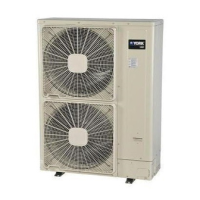
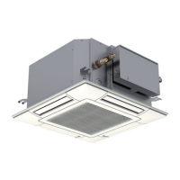
On the water source unit Printed Circuit Board (PCB), there are three input terminals (CN17, CN18 as
shownbelow)toreceiveexternalsignalsandtwooutputterminals(CN16)tosendsignalsout.Control
functions shown in these tables are available when setting input and output terminals.



 To Next Page