SM-18006
5-5
EXTERNAL INPUT/OUTPUT AND FUNCTION SETTING
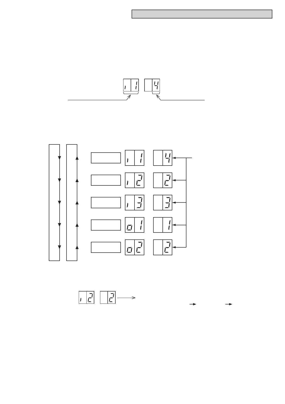
(2) BypressingPSW2orPSW4,theinput/outputterminalnameischanged.
The following shows the display changes when PSW2 or PSW4 is pushed.
(4) AfterselectingtheControlFunctionNo.,turnOFFDSW4-No.6.Thedisplaywillbebacktothenormal
operation.ThenturnOFFtheDSW4-No.4.ConrmiftheDSW4issettofactorysettings.Theselected
dataisstoredinthewatersourceunitPCBandthe“ExternalInputandOutputSetting”iscompleted.
The stored data is maintained even when the power supply is cut OFF. Refer to Table 5.1 below for
the details for the electrical wiring connection and the required parts.
If an alternative setting is required at a site, perform the following procedures.
(1) Byselecting“ExternalInputandOutputSetting”,thefollowingappearsonthe7-segmentdisplay.
(Thesettingshouldbeperformedduringanwatersourceunitstoppage.Also,setDSW4-No.4of
the water source unit PCB to the “ON” side before performing the setting in order to prevent the
compressor activation.)
This display indicates Control Function No.4 (Flow Switch Signal) is set at input 1.
SEG2 SEG1
Input/OutputTerminalName Control Function No.
(3) AfterselectingtheInput/OutputTerminalName,pressPSW3orPSW5,andthenchoosetheControl
Function No.
By pressing PSW3, the number increases by 1.
By pressing PSW5, the number decreases by 1.
(Control Function No.14
Press PSW3 return to 0)
● SettingsforExternalInputandOutput
Input Terminal
Name 1
Input Terminal
Name 2
Input Terminal
Name 3
Output Terminal
Name 1
Output Terminal
Name 2
PSW2
ON
ON
Current setting function is indicated as
Control Function No.
(The figure is for setting at the factory.)



 To Next Page