SM-18006
3-31
TROUBLESHOOTING
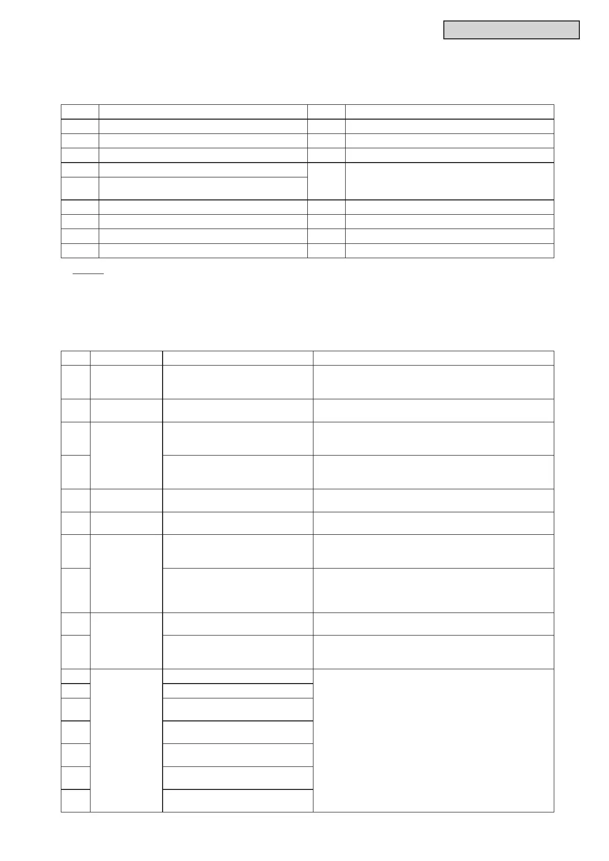
(A) Protection Control Code
The control information during operation are displayed.
The protection control code is different from the code displayed during unit operation stoppage.
(B) Alarm Code Table
Code Protection Control Code Retry Control
P01 Pressure Ratio Protection P11 Pressure Ratio Decrease Retry
P02 High Pressure Increase Protection P12 Low Pressure Increase Retry
P03 Inverter Current Protection P13 High Pressure Increase Retry
P04 Inverter Temp. Increase Protection
P15
Low Pressure Decrease/
Discharge Gas Temp. Increase Retry
P05
Discharge Gas Temp. on Top of Comp.
Increase Protection
P06 Low Pressure Decrease Protection P16 Discharge Gas SUPER HEAT Decrease Retry
P09 High Pressure Decrease Protection P17 Inverter Trip Retry
P0A Demand Current Control P18 Retry Related to Inverter
P0d Low Pressure Increase Protection P31 Abnormality of Entering Water Temp. Retry
NOTE:
Once the override (degeneration) control is activated, PC1 to PC5 is displayed instead of P01 to P05.
Code Category Content of Abnormality Leading Cause
01 Indoor Unit
Activation of Protection Device
(Float Switch)
Activation of Float Switch (High Water Level in
Condensate Pan, Abnormality of Condensate Pipe, Float
Switch, or Condensate Pan)
02
Water Source
Unit
Activation of Protection Device
(High Pressure Cut)
Activation of PSH (Pipe Clogging, Excessive Refrigerant,
Inert Gas Mixing)
03
Communication
Abnormal Communication between
Indoor and Water Source Unit
Incorrect Wiring, Loose Terminals, Disconnected
Communication Cable, Blowout of Fuse, Indoor Unit
Power OFF
04
Abnormal Communication between
Inverter PCB and Water Source
Unit PCB
Inverter PCB -Water Source PCB Communication Failure
(Loose Connector, Wire Breaking, Blowout of Fuse)
05 Supply Phase
Abnormality of Power Supply
Phases
Incorrect Power Supply, Connection to Reversed Phase,
Open-Phase
06 Voltage Abnormal Inverter Voltage
Water Source Unit Voltage Decrease, Insufcient Power
Capacity
07
Cybele
Decrease in Discharge Gas
Superheat
Excessive Refrigerant Charge, Failure of Thermistor,
Incorrect Wiring, Incorrect Piping Connection, Expansion
Valve Locking at Opened Position (Disconnect Connector)
08
Increase in Discharge Gas
Temperature
Insufcient Refrigerant Charge, Pipe Clogging, Failure of
Thermistor, Incorrect Wiring, Incorrect Piping Connection,
Expansion Valve Locking at Closed Position (Disconnect
Connector)
0C
Water Source
Unit
Incorrect Water Source Unit Main
Unit Setting
Two (or more) Water Source Units (or Outdoor Units) Set
as "Main Unit" Exist in Same Refrigerant Cycle Number
0d Water Temperature Abnormality
Insufcient Water Flow Rate, Abnormally Low Entering
Water Temperature, Insufcient Refrigerant, Piping
Clogging, Expansion Valve Locking at Close Position
11
Sensor on
Indoor Unit
Abnormality of Inlet Air Thermistor
Incorrect Wiring, Disconnecting Wiring,
Breaking Wire, Short Circuit
12 Abnormality of Outlet Air Thermistor
13
Abnormality of Freeze Protection
Thermistor
14
Abnormality of Gas Piping
Thermistor
15
Abnormality of Outdoor Air
Thermistor (EconoFresh)
16
Abnormality of Remote Sensor
(DOAS)
17
Abnormality of Thermistor Built-in
Remote Controller (DOAS)



 To Next Page