3-32
SM-18006
TROUBLESHOOTING
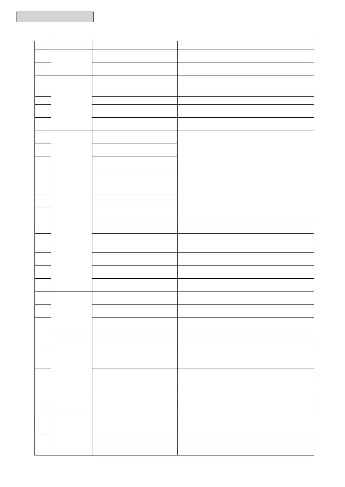
Code Category Content of Abnormality Leading Cause
18
Indoor Fan
Motor
Abnormality of Indoor Fan System
Abnormality of Indoor Fan Motor (Step-Out),
Indoor Fan Controller Failure
19
Activation of Protection Device for
Indoor Fan
Fan Motor Overheat, Lockup
1A
Indoor Fan
Controller
Abnormality of Fan Controller Fin
Temperature
Abnormality of Fin Thermistor or Fan Controller,
Heat Exchanger Clogging, Abnormality of Fan Motor
1b Activation of Overcurrent Protection Abnormality of Fan Motor
1C Problem with Current Sensor Abnormality of Fan Controller Current Sensor
1d Activation Fan Controller Protection
Driver IC Error Signal Detection, Instantaneous
Overcurrent
1E
Abnormality of Indoor Fan
Controller Voltage
Indoor Voltage Decrease, Insufcient Capacity of Power
Supply Wiring
21
Sensor on
Water Source
Unit
Abnormality of High Pressure
Sensor
Incorrect Wiring, Disconnecting Wiring,
Breaking Wire, Short Circuit
23
Abnormality of Discharge Gas
Thermistor on Top of Compressor
24
Abnormality of Heat Exchanger
Liquid Pipe Thermistor
25
Abnormality of Heat Exchanger
Gas Pipe Thermistor
29
Abnormality of Low Pressure
Sensor
2A
Abnormality of Entering Water
Thermistor
2b
Abnormality of Electrical Box
Thermistor
30
System
Incorrect Connection of Change-
Over Box
Connection of Generation 1 Change-Over Box to Water
Source Unit
31
Incorrect Capacity Setting of Water
Source Unit and Indoor Unit
Incorrect Capacity Setting of Water Source Unit and
Indoor Unit, Excessive or Insufcient Indoor Unit Total
Capacity Code
35 Incorrect Setting of Indoor Unit No.
Duplication of Indoor Unit No. In same Refrigerant Cycle
Number
36
Incorrect of Indoor Unit
Combination
Indoor Unit is Designed for R22
38
Abnormality of Picking up Circuit
for Protection in Water Source Unit
Failure of Protection Detecting Device (Incorrect Wiring of
Water Source Unit PCB)
3A
Water Source
Unit
Abnormality of Water Source Unit
Capacity
Water Source Unit Capacity > 216MBH
3b
Incorrect Combination of Water
Source Unit
Incorrect Connection between Water Source Unit,
Incorrect Setting of DSW
3E
Abnormal Combination between
Inverter PCB and Water Source
Unit PCB
Incorrect Combination between Inverter PCB and Water
Source Unit PCB
43
Protection
Device
Activation of Pressure Ratio
Decrease Protection
Defective Compression (Failure of Compressor or
Inverter, Loose Power Supply Connection)
44
Activation of Low Pressure
Increase Protection
Overload at Cooling, High Temperature at Heating,
Expansion Valve Locking at Open Position (Loose
Connector)
45
Activation of High Pressure
Increase Protection
Overload Operation (Heat Exchanger Clogging), Pipe
Clogging, Excessive Refrigerant, Inert Gas Mixing
47
Activation of Low Pressure
Decrease Protection
Insufcient Refrigerant, Piping Clogging, Expansion Valve
Locking at Close Position (Loosen Connector)
48
Activation of Inverter Overcurrent
Protection
Overload Operation, Compressor Failure
51 Sensor Abnormal Inverter Current Sensor Current Sensor Failure
53
Inverter
Inverter Error Signal Detection
Driver IC Error Signal Detection (Protection for
Overcurrent, Voltage Decrease, Short Circuit),
Instantaneous Overcurrent
54 Abnormality of Inverter Temperature
Abnormal Inverter Thermistor,
Heat Exchanger Clogging, Cooling Fan Failure
55 Inverter Failure Inverter PCB Failure



 To Next Page