3-10
SM-18006
TROUBLESHOOTING
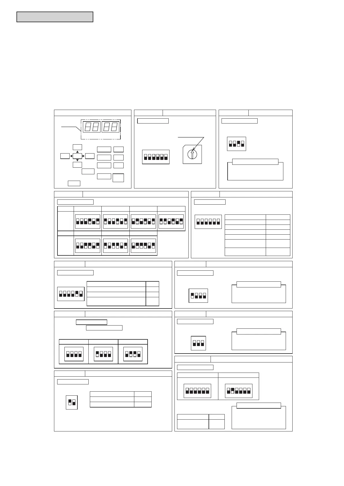
3.1.3 Checking Rotary Switch and DIP Switch Settings
The following diagram indicates the factory settings of DSWs on PCBs in the indoor and water source units.
When simultaneous operation control of multiple units or room thermostat (thermo) control is operated, the
DSW setting is different as shown below.
(1) Water Source Unit (factory setting)
Turn OFF all power supplies before the setting.
Without turning OFF all power supplies, the changes are not recognized and the settings are invalid.
(However, DSW4, 5, 8 and push switches can be operated while the power supply is ON.)
The “
n
” mark indicates positions of DIP switches.
Figure 3.3 DSW Setting
1 3 4
ON
2 65
1 3 4
ON
2 651 3 4
ON
2 65
Setting Item Pin No.
Capacity 72 MBH 96 MBH
144 MBH120 MBH
DSW2
Setting
1 3 4
ON
2 65
1 3 4
ON
2 65
1 3 4
ON
2 651 3 4
ON
2 65
Capacity 168 MBH 192 MBH 216 MBH
DSW2
Setting
Except No.1 Comp. (MC1) Operation
Except No.2 Comp. (MC2) Operation
1
2
Cancelation of Flow Switch Detection
during Water Source Unit Stoppage
5
Turn ON the DIP switch
when using the below functions.
Do not change DSW6 setting.
Otherwise, it may cause
abnormal operation.
DSW1
Tens Digit
0
7
9
5
8
6
4
3
Setting Position
1
2
RSW1
Last Digit
Set the Ref. Cycle No. of Water Source Unit
at each refrigerant cycle.
(Setting before shipment is Ref. Cycle No.0.)
Ref. Cycle No. Setting Function Setting
Setting Before Shipment
Power Supply Setting
230V Setting Before Shipment208V Unit:
230V, 460V Unit:
Test Run and Service Setting
DSW4 (PCB1)
For Test Run, Function Setting and
External Input/Output Setting
Setting Before
Shipment
Setting Before
Shipment
Setting Before
Shipment
DSW5 (PCB1)
321 4
ON
5 6
321 4
ON
321 4
ON
321 4
ON
5 6
321 4
ON
5 6
Emergency Operation and Function Setting
Single Setting
(Setting Before Shipment)
Capacity Setting
DSW2 (PCB1)
DSW7 (PCB1)
Arrangement of DIP Switches (PCB1)
SEG2
PSW3
SEG1
DSW4
Display
(7SEG)
DSW2
DSW5
DSW7
DSW3
DSW6
PSW2
PSW1
PSW4
PSW5
DSW1
DSW10
DSW8
RSW1
Enter
Power Supply Voltage Setting
208V 230V 460V
Water Source Unit No. Setting
DSW6 (PCB1)
Setting is required.
Setting is required.
No Setting is required.
No setting is required.
No setting is required.
No setting is required.
No setting is required.
Setting is required.
No Setting is required.
IMPORTANT NOTICE
Do not change DSW8 setting.
Otherwise, it may cause
abnormal operation.
IMPORTANT NOTICE
Do not change DSW3 setting.
Otherwise, it may cause
abnormal operation.
IMPORTANT NOTICE
Setting Item Pin No.
Test Cooling Operation
Test Heating Operation
External Input/Output
Setting
Refrigerant Recovery/
Vacuum Mode
1
1, 2
4, 6
4, 5
4
(+ PSW4 for 3sec.)
Compressor Forced Stop
Function Setting
4
Setting Before
Shipment
DSW8 (PCB1)
321
ON
Function Setting
Setting is required.
Setting Item Pin No.
End Resistance Setting
*1
Fuse Recovery
*2
1
2
Set DSW10-1 correctly
for end resistance cancellation.
Setting Before
Shipment
DSW10 (PCB1)
21
ON
Communication Setting
*1: Set No.1 pin to OFF for all of Water Source Unit
(or Outdoor Units) in the same H-LINK except
one Water Source Unit (or Outdoor Unit).
*2: If the fuse (EF1) is melted, set No.2 pin to ON
for recovery.
321 4
ON
5 6 321 4
ON
5 6
INV1 INV2
No setting is required.
Setting Item Pin No.
Cancellation of
Current Detection
1
Setting Before Shipment
DSW101 (INV1, 2)
Setting Before Shipment
INV No. Setting/Service Setting
If Cancellation of Current
Detection is set, make sure
to return the setting, after
service works.
IMPORTANT NOTICE
Turn ON the DIP switch when
using the below functions.
321 4
ON
321 4
ON
321 4
ON



 To Next Page