5-6
SM-18006
EXTERNAL INPUT/OUTPUT AND FUNCTION SETTING
•SettingExample
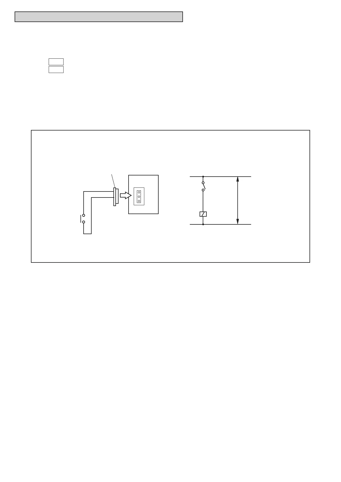
FixingHeatingOperationatInput1(between1and2pinsofCN18)
FixingCoolingOperationatInput2(between1and2pinsofCN18)
● ExternalInputFunctionSetting
The following signals can be received by the water source unit PCB. Refer to Table 5.1 below for the
required main parts.
(1)
Input
Fixing Heating Operation Mode (Control Function No.1),
Input
Fixing Cooling Operation Mode (Control Function No.2)
When the input terminals for the setting operation mode on the water source unit PCB are short-circuited,
the operation mode can be set at the cooling or heating mode.
ShortCircuitbetweenTerminals1and2ofCN18: FixedHeatingOperationMode
orFixedCoolingOperationMode
During this set heating (or cooling) mode, no cooling (or heating) operation is possible. The indoor units
under the cooling or dry operation (or heating operation) will be changed to the Thermo-OFF condition
during this mode, and stoppage code No. “20” is given.
Control Circuit
1
2
1
2
3
3P Connector
PCB
CN18
Wiring Diagram Example of Fixing Operation Mode
SS3
Power
Supply
X1
X1: Auxiliary Relay
SS3: Operation Mode Fixing Switch



 To Next Page