SM-18006
5-7
EXTERNAL INPUT/OUTPUT AND FUNCTION SETTING
(2)
Input
Demand Stoppage (Control Function No.3),
Input
Forced Stoppage (Control Function No.5)
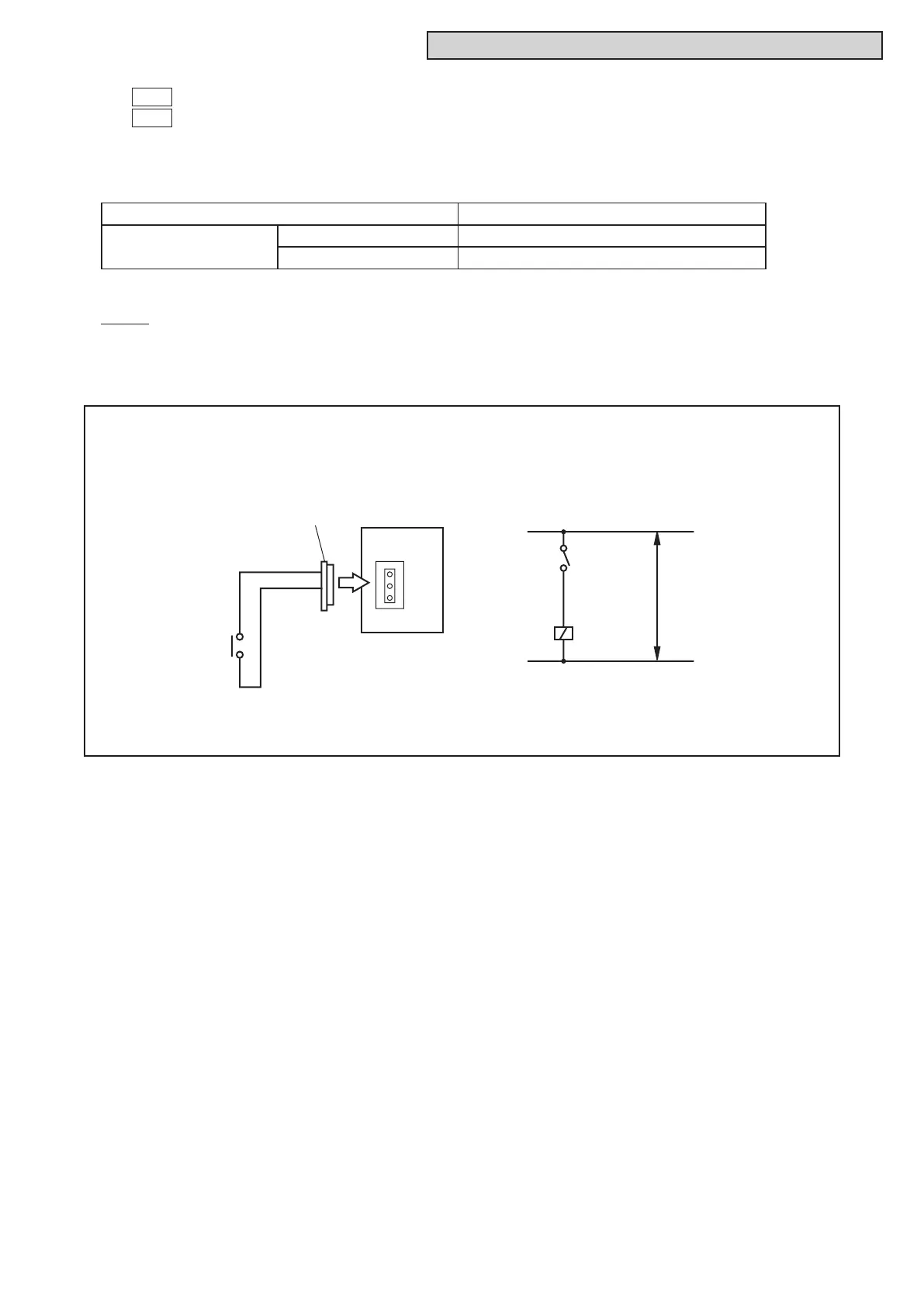
When the input terminals for Demand Stoppage or Forced Stoppage on the water source unit PCB are
short-circuited while running, the compressor(s) is stopped. The fan motor of indoor unit(s) is operated as
shown below.
The stoppage code No. “10” is given. In this case, if the input terminals are opened, operation is resumed.
NOTE:
Whendemandcontrol(ON/OFF)isperformed,itisrecommendedthatthecontrol(ON/OFF)timeisset
appropriatelyaccordingtotheheatload.Also,setthedemandcontroltimeapproximatelyoncein15
minutes at the minimum in consideration for saving energy.
•SettingExample
Demand Stoppage at Input 3 (between 1 and 2 pins of CN18)
Forced Stoppage at Input 3 (between 1 and 2 pins of CN18)
Demand Stoppage (Control Function No.3) Cooling:AirowSetting,HeatingLoSetting
Forced Stoppage
(Control Function No.5)
Function Setting “FE”=0 Stop
Function Setting “FE”=1 Cooling:AirowSetting,HeatingLoSetting
Control Circuit
1
2
1
2
3
3P Connector
PCB
CN18
Wiring Diagram Example of Demand Stoppage or Forced Stoppage
SS3
Power
Supply
X1
X1: Auxiliary Relay
SS3: Demand Stoppage Switch



 To Next Page