(Main Parts)
MAINTENANCE
4-98
SM-18006
● Specications for MVB
Model UKV-U040E or UKV-A035
Working Temperature
Range
-22
o
F to 158
o
F (-30
o
C to 70
o
C)
Refrigerant Used R410A
Insulation Resistance Min. 100M
Ω
(at 500VDC Megger)
Withstand Voltage 1800VAC for 1 Second
Rated Voltage
DC12V+1.2V
Drive Condition
83+5 PPS
1-2 Phase Excitation
Coil Resistance
46+3Ω (at 68
o
F (20
o
C))
Insulation Class Class E
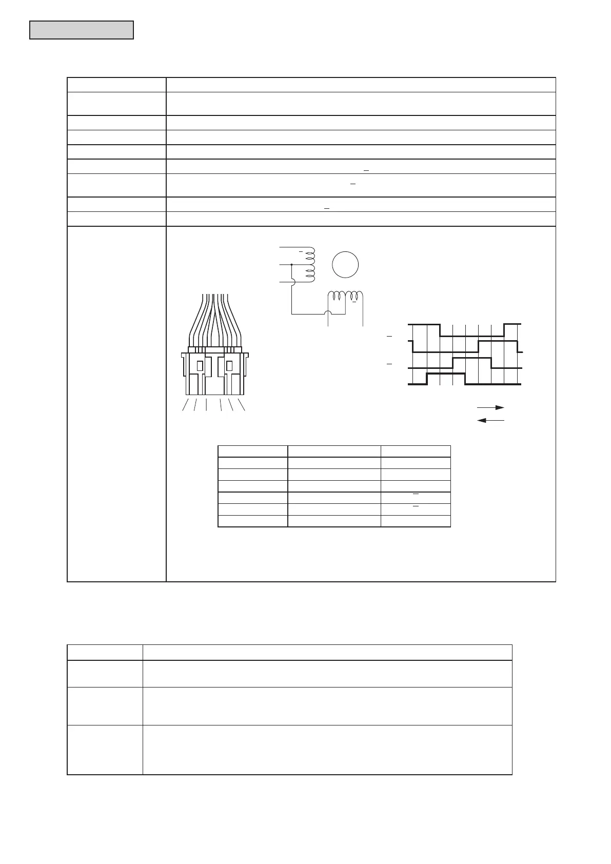
Wiring Diagram,
Drive Circuit and
Activation Mode
B
(1)
(6)
A
(3) (5)
M
B
A
Red
ON
B (6)
Valve Operation
Direction
1234 5678
Open
A (3)
B (4)
A (5)
Order of Excitation (1-2 Phase Excitation)
Connector No. Color of Lead Wire Phase
1 Gray Common (+)
2 - -
3 Orange A
4 Black B
5 Yellow A
6 Red B
● Checking Method of Electronic Expansion Valve
Water Source Unit Electronic Expansion Valve
Locked
(Fully Closed)
It is abnormal if the liquid pipe pressure does not increase during cooling operation.
Locked
(Slightly Open)
It is abnormal if the liquid pipe pressure does not increase and the outlet
temperature of the expansion valve decreases after the cooling operation is
started.
Locked
(Fully Open)
It is abnormal under the following conditions. After heating operation for more than
30 min., the discharge gas temperature of compressor is not 50
o
F (10
o
C) higher
than the condensing temperature. There is no other fault such as excessive charge
of refrigerant.
< Checking Method >
Measure the coil resistances between connector No.1 (common) and each phase.
The measured resistance value is normal if approximately 46Ω
*)
.
( *): Ambient Temperature 68
o
F (20
o
C))



 To Next Page